Continue to Site

Welcome to EDAboard.com

Welcome to our site! EDAboard.com is an international Electronics Discussion Forum focused on EDA software, circuits, schematics, books, theory, papers, asic, pld, 8051, DSP, Network, RF, Analog Design, PCB, Service Manuals... and a whole lot more! To participate you need to register. Registration is free. Click here to register now.

Balun balanced to unbalanced impedance transformation

Status
Not open for further replies.

marvin1

Newbie level 5
Joined
Nov 11, 2010
Messages
8
Helped
0
Reputation
0
Reaction score
0
Trophy points
1,281
Activity points
1,355
Hello,

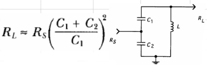
I am using SA612 mixer for down conversion, Before the mixer I have image filter that is designed using coupled resonators. In SA612 datasheet the proposed circuit is to match the single input to differential output is a LC balun network, however I do not understand the math behind it. And the circuit in datasheet looks different from typical circuits in Vizmuller book or the one's I googled.

Could anyone explain where 220 pf, 47 pf and 0.2 uH inductor comes from. Thank you in advance.

Oh, here is a datasheet to SA612.
 

Attachments

  • SA612.pdf
    117 KB · Views: 116

In fact this is not balun configuration, because pin 2 of SA612 is AC connected to the ground (reactance of 100nF looks almost as a short at RF frequency).

This is a capacitive tap impedance matching, which is using the formula as in the attached picture (this is valid only if Rs < RL).
72_1293040393.jpg


If input impedance is 50 ohms result about 1.6kohm impedance of pin nr 1 (SA612).

Caps 47pF in series with 220pF (and some input capacitance of pin 1), all in parallel with 280nH inductor, should resonate on 45MHz, which is the IF input frequency.
 
Thank you for a quick response,

I used Thomas Lee book to estimate the values I need for 38.2 MHz with bandwidth of 2 MHz, therefore Q is 19.1. However I end-up with 1.3 k ohm. The other problem is that I only have 150nH, 220 nH, 1.2uH variable coils.

I have done calculations that are attached to message. Is this correct? and The capacitor values are much different from the datasheet. When I use 150 nH, the impedance is matched to 1.4 k, but when I use 1.2 uH, its around 432 kohm. Where did I go wrong?

Another question about this mixer is the fundamental trap (bandstop filter LC in series on oscillator input). How would I determine which frequency I need to remove, how would I determine the fundamental frequency if my oscillator is in 3rd overtone mode?? I would assume its 34.545 MHz divide by approximately 3 (around 10 MHz), but In datasheet the filter resonate at 4.4 to 7 MHz. My 3rd overtone crystal oscillate at 48.9 MHz, where should the LC filter resonate, at which frequency?


First up, the equation posted up by vfone is only an approximation. It is commonly used but there are more accurate equations than this for a capacitive tap impedance match.
Second, the app note can't possibly be peaked to work at 45MHz with the values shown even with 280nH. It won't tune down to 45MHz. Therefore it relies on the self capacitance of the device itself.

If you want to match 50R to your 1500R Philips part at 38MHz then you are also going to also have to take into account the parallel resistance of the inductor due to finite Q.
Therefore you will probably have to match to something like 1100R rather than 1500R.

From your range of coils available the only one that comes close is the 220nH one. Using this in a capacitive tap to match to 1100R at 38MHz requires
C1 = 100pF
C2 = 360pF
L1 = 220nH (assuming Q= 100 approx and this might be hard to realise)

In practice you will have to tune the 220nH inductor down to maybe 210nH to account for the 3pF of the Philips part and centre the response on 38MHz.

This will just about meet your 2MHz BW requirement although it will show about -1.5dB of droop at 37 and 39MHz.

The match will be quite poor at 37 and 38MHz. You really need to redesign using a bigger inductor if this is a problem. eg:

C1 = 56pF
C2 = 200pF
L1 = 390nH (assuming Q= 60 approx and this should be typical with a tunable coil)

This will give a wider bandwidth :)

In practice you will have to tune the 390nH inductor down to maybe 360nH to account for the 3pF of the Philips part.

Note: The very first impedance matching program I ever wrote for a computer was for a capacitive tap network and this was a very long time ago :lol:

---------- Post added at 23:06 ---------- Previous post was at 21:28 ----------

If you resort to an L match you could use C1 as 12pF and L1 as 1.2uH (C2 not fitted)

This would give a reasonable match and good bandwidth.

If you can tune the 1.2uH down to 1.1uH and increase C1 to 14pF then the match gets better.
 
Last edited:
Hello again,

Thank you for a quick response. I was on vacation now back to the problem. I couldn't find a better source for capacitive tap network then Thomas Lee book. Could you recommend something else? Because I tried his method and the values I come up with different then yours. Unfortunately the inductors have a Q of minimum 45, the only tunable inductors avaliable to me at the moment. Actually the bandwidth can be narrower. And also about the second question - fundamental trap for mixer that I wrote previously, how do I determine which frequency I need to remove, how would I determine the fundamental frequency if my oscillator is in 3rd overtone mode at 48.9 MHz??

---------- Post added at 15:10 ---------- Previous post was at 15:09 ----------

I already have the PCB ready. I can switch to L match, with Q of 5 quite small. I need to undestand the calculations though behind capacitive tap network, so that I can compare which one is better. And if I use L match i connect on end of coil to one input port and the other end of coil to ground and to second input port of mixer. Is that going to be differential impedance transformation though?
 
Last edited:

Status
Not open for further replies.

Part and Inventory Search

Welcome to EDABoard.com

Sponsor

Back
Top