wee85
Junior Member level 1
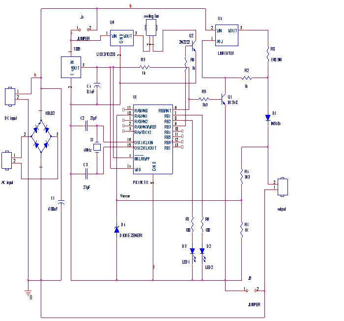
lm317 pulse charge
hi dexter dude, can u tell me the component of battery charger function of the smart battery charger u attach in this forum and how the circuit operate? Thanks...
hi dexter dude, can u tell me the component of battery charger function of the smart battery charger u attach in this forum and how the circuit operate? Thanks...
")