Continue to Site

Welcome to EDAboard.com

Welcome to our site! EDAboard.com is an international Electronics Discussion Forum focused on EDA software, circuits, schematics, books, theory, papers, asic, pld, 8051, DSP, Network, RF, Analog Design, PCB, Service Manuals... and a whole lot more! To participate you need to register. Registration is free. Click here to register now.

[updated!]U-slot on patch antenna for bandwidth enhancement

Status
Not open for further replies.

DrunkBear

Advanced Member level 4
Joined
Dec 14, 2006
Messages
108
Helped
11
Reputation
22
Reaction score
4
Trophy points
1,298
Location
HangZhou,China
Activity points
2,115
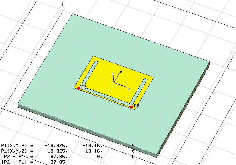
need a patch antenna design with u slot

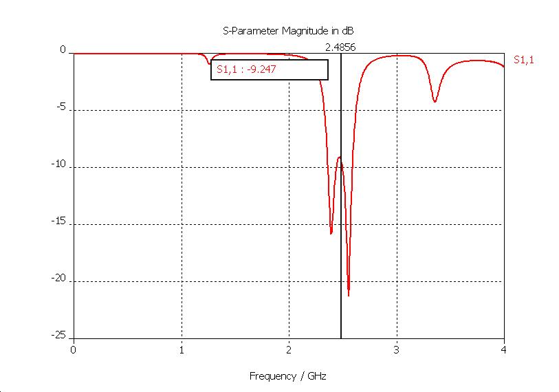
Once i tried to etch a U-slot on a well matched bottom-fed antenna, the S11 result turned to be extremely bad.

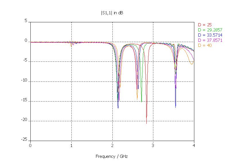
are there any guidelines for U-slot (or other shape of the slot) technique, which is used to enlarge the bandwidth of the patch antenna? Most paper i found just give the final parameters but would not tell the design steps: e.g how the length/width/slot width should be determined.

Any advice?Thank you in advance!
 

u slot patch antenna

Hi DrunkBear,
I found that the book, names Microstrip Antenna Design Handbook - Chapter 7 - Artech House, has your topic.

This book is already available at:
**broken link removed**

I hope it will help you.

Regards!
 
patch antenna bandwidth enhancement

There are numerous references to u-slots in patches as bandwidth enhancers in the IEEE Transactions on Antennas and Propagation. I have occasionally found slots and various cutouts helpful and they can enhance bandwidth.

The MTT Transactions also have related references.

I would start by searching the archives "www.ieee.org".

Start there and I am certain you will find enough to guide you to a solution.
 

    DrunkBear

    Points: 2
    Helpful Answer Positive Rating
antenna parasitic element increases bandwidth

nhomuathu_hanoi said:
Hi DrunkBear,
I found that the book, names Microstrip Antenna Design Handbook - Chapter 7 - Artech House, has your topic.

This book is already available at:
**broken link removed**

I hope it will help you.

Regards!

hi nhomuathu_hanoi,

It's very kind of u for supplying the link to download this book, yet unfortunately i cannot connect this address and open.
i wonder if u could change to another online harddisk for me?
Thank u very much!
also thanks to Azulykit for ur advice!
 

patch antenna wide bandwidth air

Hi DrunkBear,

I'm sorry for my late.
Plz give me your email, I can share it directly or you can find it by Emule.

I also have some papers that discuss about U slot antenna. PM if you want.

Best regards!
 

why slot on patch can increase the bandwidth

i examined some literature, suggested and recommended by the warm-hearted people, as those who replied me.
what i feel like doing now is connect the two neighbouring resonance-2.17GHz and 2.6GHz together, forming a relatively broadband centered in 2.3GHz.


At the very beginning, i succeeded in moving the higher resonance downward, from more than 3GHz to 2.6GHz, by increasing the length of bottom side of the U-Slot(noted by D). However, the bottleneck now is this trend just fades out when D is increased over about 33mm and i hardly find any method to get the resonance frequency further decreased.

The other parameters ajustable seem dumb to this optimization.
Could u pls analyze why this happens and help me get a breakthrough?
Thank you!
 

microstrip antenna bandwidth enhancement

hi DrunkBear,

I have an opinion. If you don't mind, let try to put another substrate, I mean that's a dielectric layer, at the top of your antenna. Maybe, it's a stupid ideal but I guess S11 diagram will be moved to the left. It means that the resonated frequency will be decreased although you don't have to increase your antenna's size. And I think, it is not difficult for you to increase the lower resonated frequency after.

regards!
 

microstrip antenna u slot

hi nhomuathu_hanoi,

sorry, but i don't quite understand what "to put another substrate--a dielectric layer-- at the top of your antenna" is. you mean the patch is just between the two dielectric layers, the whole strucure being like a sandwich? can you explain the reason?
4mm thickness of the substrate is my limitation that i cannot exceed, which is just my difficulty to enhance the BW.
as i showed in the previous post, what i'm rather eager to know is the reason why the 2.6GHz resonant frequency cannot be lowered any more. i checked the surface current on the patch. Indeed the bottom side of the U-slot is exact the 1/2 resonant length at this frequency.
up to now, it seems to remain just a little step from my goal and you know it feels extremly terrible if i cannot get clear the reason that caused the bottleneck.


Thanks for your reply and suggestion!
 

u slot microstrip patch antenna papers

u need to chage the patch dimensions. The problem bottome edge frequency is fading out since the current patch and feed is not providing match at the two resonances
 

    DrunkBear

    Points: 2
    Helpful Answer Positive Rating
design of a patch to enhance bandwidth

As has been mentioned elsewhere increasing patch thickness and decreasing the dielectric constant to as close to air as possible will give you the most success in bandwidth enhancement.

Various slots and parasitic elements will increase bandwidth further. My experience is that this is usually experimental with some guidance from the technical literature base.

You might look into James "HDBK of Microstrip Antennas" as another reference.
 

Re: U-slot on patch antenna for bandwidth enhancement

Thanks for the share...

nhomuathu_hanoi said:
Hi DrunkBear,
I found that the book, names Microstrip Antenna Design Handbook - Chapter 7 - Artech House, has your topic.

This book is already available at:
**broken link removed**

I hope it will help you.

Regards!
 

Re: [updated!]U-slot on patch antenna for bandwidth enhancem

Azulykit said:
As has been mentioned elsewhere increasing patch thickness and decreasing the dielectric constant to as close to air as possible will give you the most success in bandwidth enhancement.

Various slots and parasitic elements will increase bandwidth further. My experience is that this is usually experimental with some guidance from the technical literature base.

You might look into James "HDBK of Microstrip Antennas" as another reference.
hi Azulykit,
many thx for your advice!
unfortunately, it is simutaneously required compact size and wide bandwidth that add an extra difficulty to my task. The limitation of the patch size does not allow me to incorporate other parasitic elements around it and the thin substrate further restricts the bandwidth.
So i'm wondering if merely etching U-slots could do the job. Because as you mentioned in your reply, many reported work apply both very low permittivity (foam, even air) and very thick (usually more than 10mm) dielectric substrate, it's not strange at all that more than 30% impedance BW could be achieved.
i'm considering if it is possible to incorporate the L-probe fed, but still doubt the feasibility when it is applied in a thin and high epsilon substrate.
This is the best result i get up to now:
 

Re: [updated!]U-slot on patch antenna for bandwidth enhancem

The world always wants smaller antennas that work better. People in Hell want ice water too. This is the bane of the antenna engineer.

Slots, cuts and various feed schemes can get you to patches in the 30 to 35% bandwidth range.

Parasitic elements can get a little more bandwidth. So far the upper limit seems to be around 50% using a combinatiion of the variious tricks and some expermentation. Sit down with a good simulator and play,
 

Re: [updated!]U-slot on patch antenna for bandwidth enhancem

i shall keep making efforts and tell you the lastest progress.
thank you!
 

Re: [updated!]U-slot on patch antenna for bandwidth enhancem

Hello,

Your resiults look great. Can you share with me your design detail. How did you select the U-slot size and placement, etc and if possible your antenna parameters.

Thanks in advance
 

nhomuathu_hanoi said:
Hi DrunkBear,
I found that the book, names Microstrip Antenna Design Handbook - Chapter 7 - Artech House, has your topic.

This book is already available at:
**broken link removed**

I hope it will help you.

Regards!


I've been looking for this book for a long time. Thanks man.

Added after 1 minutes:

lol, it's a scanned version from China. Good good~
 

hi. i have made an aperture coupled microstrip patch that works on 2.28Ghz in HFSS.
now i want to make it work on 2.45 Ghz.
someone told me to use optimetrics.
but i dont know how.
can u help?
 

Clearly the antenna is too heavy. Adjust the dimensions so that it weighs less. Scale the weight the inverse of the relative frequency change. As the weight decreases the resonant frequency will increase.

You could probably make the adjustments without HFSS/Optometrics. An xacto knife and a VNA would work too, with a bit of copper tape if you get too enthusiastic.
 

i also want to increase bandwidth of patch antenna and want to make u slot. but i have no idea how to make slot and what is dimension of that....
please help it.....
where i found method for that ?
 

Status
Not open for further replies.

Part and Inventory Search

Welcome to EDABoard.com

Sponsor

Back
Top