Continue to Site

Welcome to EDAboard.com

Welcome to our site! EDAboard.com is an international Electronics Discussion Forum focused on EDA software, circuits, schematics, books, theory, papers, asic, pld, 8051, DSP, Network, RF, Analog Design, PCB, Service Manuals... and a whole lot more! To participate you need to register. Registration is free. Click here to register now.

Question on RF Passive Filter Design

Status
Not open for further replies.

wizardz

Member level 2
Joined
Aug 5, 2006
Messages
52
Helped
0
Reputation
0
Reaction score
0
Trophy points
1,286
Activity points
1,740
passive filter

My target is to design a RF passive filter operating at

center freq = 8GHz
-3dB Bandwidth = 300MHz
Insertion Loss <= 0.8dB

my goal is to try using an integrated novel MEMS inductor and MIM cap.
But i found the circuit require >30nH inductor which is hard to implement.

I would appreciate very much if you give me some suggestion.
Are there better circuit topologies?
Thankyou!!!

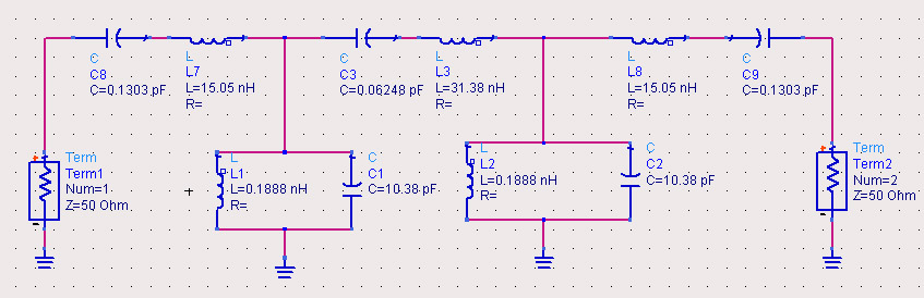
now i am trying a 5 order Chebyshev filter as follow
 

mimcap tolerance

did u try to use TX lines instead of , inductors

khouly
 

rf passive filter design

The problem is that the filter you designed is so narrowband that the accuracy requirements of your series and shunt resonators are very high. Look for example at the ratio of capacitors and inductors you need to make; this is a factor 100. The small values suffer from parasitic effects, the big values require a lot of physical space (high cost). Moreover the tolerance on the low values will always be too high to obtain the resonator ferquency accuracy required for such a high-Q filter.

All depends on the technology you're using and its accuracy (tolerances). Monte-carlo simulation can give you a better view on this.
 

    wizardz

    Points: 2
    Helpful Answer Positive Rating
application of passive filter

Hello,


Go thru the following websites...
h**p://www.circuitsage.com/filter.html
and
h**p://www.filter-solutions.com/


---manju---
 

    wizardz

    Points: 2
    Helpful Answer Positive Rating
passive filter designer

Thank you for your suggestions!

Does it mean the filter is so narrowband that it is hard to implement?
According to IEEE articles, I found CMOS process can fabricate on-chip
spiral inductors as large as 100nH.

How do people achieve this kind of design gaol, use an active filter instead?
 

rf lc resonant filter design

Have you considered the self-resonant frequency of this inductor?


spiral inductors as large as 100nH
wizardz said:
Thank you for your suggestions!

Does it mean the filter is so narrowband that it is hard to implement?
According to IEEE articles, I found CMOS process can fabricate on-chip
spiral inductors as large as 100nH.

How do people achieve this kind of design gaol, use an active filter instead?
 

inductor self resonant frequency filter

hi, dingjingfeng

I think the self resonant frequency is dependent on parasitics of the inductor,
which is hard to control.

Plus,if we let a circuit work at the self resonant frequency, the network might have high insertion loss.

Does the "self resonant" design method really exist?
 

designgaol.dk

you can try the following topology:
(1)Resonator is realized by parallel LC resonant circuit
(2)the coupling,including input/output coupling, interstage coupling, are realized by capacitors.
 

design gaol

At that frequency, LC filters are practically impossible. Instead, Hairpin or edge coupled or similar Lumped Element Filters should be used..
For these filters,look at that book that is available in elektroda..

Microstrip Filters for RF/Microwave Applications. Jia-Sheng Hong, M. J. Lancaster
Copyright © 2001 John Wiley & Sons, Inc.
ISBNs: 0-471-38877-7 (Hardback); 0-471-22161-9 (Electronic)
 

Hi,

I think you need high Q-factor components to design the filter with such narrow bandwidth. Your CMOS inductors are probably not good enough.

flyhigh
 

.8 db of iL at 8 ghz and 300 mhz bandwidth, does not sound achivable,
just off the top of my head. a combline cavity perhaps, or interdigital perhaps

but upon implementation youre gonna get more than .8 dB

also, typically you change the resonators in such as way as to minimize the
inductors.

if that works please let me know, thanks
 

Status
Not open for further replies.

Part and Inventory Search

Welcome to EDABoard.com

Sponsor

Back
Top