Continue to Site

Welcome to EDAboard.com

Welcome to our site! EDAboard.com is an international Electronics Discussion Forum focused on EDA software, circuits, schematics, books, theory, papers, asic, pld, 8051, DSP, Network, RF, Analog Design, PCB, Service Manuals... and a whole lot more! To participate you need to register. Registration is free. Click here to register now.

Short circuit in a Switched power supply /charger

Status
Not open for further replies.

hafrse

Full Member level 3
Joined
Aug 6, 2007
Messages
169
Helped
1
Reputation
2
Reaction score
3
Trophy points
1,298
Activity points
2,413
Hello,

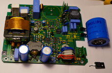
I have a power supply/charger for an instrument, I have no history of it but when charging the instrument (12V NiCd battery) today, I noticed that the charger was quite hot, not sure if that is normal since I only had this charger for a couple of days.
I switched off and powered back again, the fuse (1A) went off very fast. I located the fault in the MOSFET tranansitor Q3 where all the pins were shorted!
No problem to replace Q3 but any clue what caused that? should I look on the other side of the transformer in case of som kind of short or heavy load in that circuit?

Thanks!
 

Attachments

  • NCC.jpg
    NCC.jpg
    509.2 KB · Views: 248

you say you switched off then back on again......so when you switched back on, the NTC would have been warm, and there would have been potentially very high inrush into the 270uF primary capacitor...which could have blown the 1A fuse.....especially if you inadvertently switched back on at the peak of the mains.

But you say the fet pins are shorted...all 3.....uummmm.

Was your sec feedback working?.......the LT1241 has no overload protection....no timeout function
 

    hafrse

    Points: 2
    Helpful Answer Positive Rating
the 68uH choke in conjunction with the 1uF cap following could easily over volt the fet at turn on if the ntc is hot.
--- Updated ---

also -- check the source resistors
 

    hafrse

    Points: 2
    Helpful Answer Positive Rating
Please give details of your transformer.
You dont have a protection TVS across your primary clamp, so at startup, with all the staircasing, you could get a high voltage resulting on that FET.

The following course, in the "staircasing" folder gives details on "staircasing".

Also, you have no gate source 10k resistor, so at startup, before the LT1241 got power, the fet might have been fixed ON and giving a short across the rail.
Also, LT1241 only has 2v startup hysteresis, so the controller may take ages before it finally gets power, and if the fet was induced on, perhaps from the previous ON time, then it woudl just short across the rail and blow up........it looks to me that you need a controller with bigger hystereses since you are using a trickle start up with pool capacitor...eg the LT1242/LT1244 have better hysteresis.......or just use a 10k gate source resistor


Also you have a pot on your LT1241 oscillator input...that could potentially introduce noise into that pin, with subsequent malfunction.
--- Updated ---

What is the power level of your power supply/charger?
 
Last edited by a moderator:

    hafrse

    Points: 2
    Helpful Answer Positive Rating
Anyway, so its difficult to say exactly what caused the short to the fet, but attached is a re-run of your shown schematic, with what, IMHO, are some improvements. Only the salient bits are shown.
I assumed the transformer as shown, and a power of 62W. Please tell if much different.
The grounding situation with the sec side opamps didnt look so good, so i re-did it as attached....the attached is in the free LTspice simulator, and shows it at 13.5v 4.5A charging.
As discussed, the LT1241 needs swapping out really too.
 

Attachments

  • Flyback charger 62w.pdf
    181.6 KB · Views: 105
  • Flyback _charger.zip
    2.9 KB · Views: 96
  • Calcs.zip
    9.9 KB · Views: 98

    hafrse

    Points: 2
    Helpful Answer Positive Rating
you say you switched off then back on again......so when you switched back on, the NTC would have been warm, and there would have been potentially very high inrush into the 270uF primary capacitor...which could have blown the 1A fuse.....especially if you inadvertently switched back on at the peak of the mains.

But you say the fet pins are shorted...all 3.....uummmm.

Was your sec feedback working?.......the LT1241 has no overload protection....no timeout function
Hello,

Thank you so much in taking your time to answer, I did switch off and after about 1 hour, I switched on then the fuse blowed up and the 3 pins of the MOSFET were shorted. The charger was on for about 10 hrs and got hot. I am waiting for a replacement for the MOSFET to arrive. And I ordered also a new LT1241 since the MOSFET got shorted. I did not checked the feedback, not sure if that is possible to check before replacing the MOSFET , b ut I can still check now for short circuits there. Thanks
--- Updated ---

the 68uH choke in conjunction with the 1uF cap following could easily over volt the fet at turn on if the ntc is hot.
--- Updated ---

also -- check the source resistors
Thanks, I will check the source resistors. I am not sure how hot the NTSC was since it took 1 hour until I switched back again (when the fused get blown) and I recalled that the power supply was not too hot at that time
--- Updated ---

Anyway, so its difficult to say exactly what caused the short to the fet, but attached is a re-run of your shown schematic, with what, IMHO, are some improvements. Only the salient bits are shown.
I assumed the transformer as shown, and a power of 62W. Please tell if much different.
The grounding situation with the sec side opamps didnt look so good, so i re-did it as attached....the attached is in the free LTspice simulator, and shows it at 13.5v 4.5A charging.
As discussed, the LT1241 needs swapping out really too.
Thnaks, so I need to perform these steps:
1 - Check for any shorts on the sec feedback circuits, what else can I do there to test ? may be by injecting a DC 16v (after taking away CR51) to power the op amps and how can I test if the feedback is woking?
2 - Check the 2 Source resistors.
3 - Replace the LT1241 with a new one (I am waiting for a new one) and the MOSFET
4 - Redesign gounding for the sec. opamplifiers as you proposed.
5 - Put a 10k resistor between Gate and Source
6 - Replace the MOSFET (I am waiting for 4 pieces in case I fried on again :) )
 
Last edited:

if gate and drain of fet were shorted together, then that means the high voltage got to the gate pin of the LT1241......it may well have gone through the LT1241 and fried any components connected to any of the LT1241 pins...but you may be lucky.
I thought you were going to try the LT1244 because of its greater startup hysteresis?

Also, the UCC28C44 is pin for pin with LT1244, so maybe cheaper aswell.

Can you try and use your aux coil to "warn" of sec overvoltage and shut the controller down?...use a zener and a BJT, etc....

Also, you can make it so that if your sec is short, then your aux is also short, and your controller gets no power and so cant operate....(you dont want it to operate into a short)
 

Hello,

Thnaks for the information, will check the components connected to the 1241, I have already ordered the 1241 a couple of days ago, I will also try the LT1244, will place a seperate order for it. Do I need to change any components for the LT1244 ? when first I recivby the 1241, should I insert a 10K bertween G and S ? by way, you are right, the power supply is rated at max 60 Watts according to the label on it. and was not powered on for 17 years ago....
 

LT1244 is pin for pin......so no need to change anything.
If your power supply was not powered on for 17 years, then maybe the electrolytic was "leaky", and was drawing a high DC leakage current....but then again, it was the fet that blew...but then again...maybe that 'lytic was dried out and so could not damp out the switch on LC ringing...and so maybe there was overvoltage or the fet at power up. Maybe you should replace the 'lytic caps in case they are dried out.
--- Updated ---

Now I give here my free SMPS course, so you may look into it to receive help in the relevant sections...
https://drive.google.com/file/d/0B7aRNbu3Fes4TU92Mkw3YlA3ams/view?usp=sharing
 

Hello,

Yes , that what I was thinking about, you mean C11 the 220uF 385V lytic cap ?
Thanks for the link to the course :)
 

After 17 years - a hard switch on of the mains will likely damage the HV electrolytics as said above - if they are not a good capacitance this may raise the volts on the mosfet and kill it when it turns off
--- Updated ---

also if the fet blew up in a major fashion it is likely that a lot of components connected to the gate line will be fried ...
 

I agree, will replace every thing there including the elyt caps on the primary and sec. side
 
  • Like
Reactions: treez

    T

    Points: 2
    Helpful Answer Positive Rating
some observatians: While I am waiting for the componets to arrive (takes 7-10 days) , I started to unsolder the MOSFET, when I did a slight force to pull it up, the body could be drown out easily away/loose from the 3 pins ! apperantly it was overheated while in operation before it got shorted, that explains why the entire alu housing of the power supply was hot. The MOSFET is a FQPF5N90C Vdss 900V with isolated body
 

In line with your findings, it also looks like the Flyback transformer is not sandwich wound. This may have meant high leakage inductance, and high snubber losses, and high fet switching losses.
Do you have the transformer manufacture diagram?
 

    hafrse

    Points: 2
    Helpful Answer Positive Rating
I do not have any information about the transformer, attached are some pictures.
I read the manual of the instrumet (Nagra Digital tape recorder) and there it states that the DS50 (I mode LED in the sensing op amp) will light when the charger is charging and connected to the instrument with the internal 12V NiCd battery , but I remember that the LED was lighted even through the charger was not connected to the instrument (not 100% sure), could it also be an internal malfunction load in the sec. circuit which overheated the MOSFET ? before the problem , the charger was on and charging for about 8 hours.
 

Attachments

  • DSC05998.JPG
    DSC05998.JPG
    3.2 MB · Views: 159
  • DSC05999.JPG
    DSC05999.JPG
    1.2 MB · Views: 140
  • DSC06000.JPG
    DSC06000.JPG
    768.4 KB · Views: 142

Update.

Today I have replaced all the suspected components mentioned in this thread , and now it works fine!
Thanks all for those who helped me in this thread
 
Last edited:
Hello,

I now started to charge the battery with this charger, I noticed that the primary transformer T1 is becomming very hot after about 30 min charging, not sure if that is normal. when not charging(standby) , it is not hot.
Any idea?

thanks!
 

Attachments

  • DSC05998.JPG
    DSC05998.JPG
    3.2 MB · Views: 119

another question where no answer is possible without a lot more information, how hot is hot ? 250 deg C
 

    hafrse

    Points: 2
    Helpful Answer Positive Rating
Hello,

If I measure on the copper shield of the transformer (se picture above) , after 30 min the temperature is about 50 Deg C, but I suspect it is higher when the power supply is boxed in it Alu encloser . may be that is ok, not sure. The charger charges a Nicd 12V battery at 16V 400mh according to the manual.
--- Updated ---

Now had gone about 2 hours , stablizes at 51 Deg C. In the closed aluminium encloser , there are no fans or vents...

How hot can these types for transformers will get?
 
Last edited:

Status
Not open for further replies.

Similar threads

Part and Inventory Search

Welcome to EDABoard.com

Sponsor

Back
Top