Continue to Site

Welcome to EDAboard.com

Welcome to our site! EDAboard.com is an international Electronics Discussion Forum focused on EDA software, circuits, schematics, books, theory, papers, asic, pld, 8051, DSP, Network, RF, Analog Design, PCB, Service Manuals... and a whole lot more! To participate you need to register. Registration is free. Click here to register now.

Square wave to DC conversion

Status
Not open for further replies.

ark5230

Advanced Member level 3
Joined
Jun 29, 2009
Messages
862
Helped
163
Reputation
324
Reaction score
140
Trophy points
1,323
Location
India
Activity points
6,187
I am using approx 1 KHz square wave signal from a detector giving 50 to 60 mV into a load of 3.3K ohms.
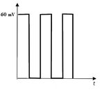
Square wave.jpg

I wish to construct amplifier that can give approx 5 V DC output so that it can be used with ADC.
Single supply like LM358 is desirable. I am not getting how to tackle this issue !
A hint how to go about or link to resource will be helpful
 

Hi,

Could you use a non-inverting amplifier to amplify to about 5V? If it's a 1kHz signal, and the op amp is fast enough the square wave won't be spoiled.

Not sure if a gain of 83 is a bad idea for any reason, if it were you could cascade a couple of op amp gain stages. 1k/82k would give a gain of 83 (60mV > ~4.8V).

If the precise value of the ADC signal is not so important, perhaps even just using a comparator to output high 5V, low 0V would be enough.
 
Hi,

Square wave.. like shown..

But what do you mean by "square wave to DC"?
DC is not a frequency. It is a straight line.
A 7805 voltage regulator generates 5V DC...

You could transform the square wave into something like DC with an averaging filter, or by RMS calculation.
Averaging gives 50% of initial amplitude.
RMS gives 70.7% of initial amplitude.
(Assuming 50% duty cycle)

Klaus
 
You're putting this into an ADC so you must be measuring something but you don't say what. Duty cycle? Amplitude? What bandwidth do you need to measure?

It's quite straightforward to filter the square wave with an RC filter and then amplify it. But how exactly you'd do this depends on the questions above.
 
Extremely sorry for delay as I was out of station.
@d123
Yes I am trying to do that the two opamps in cascade to provide a gain in the range of 60 to 100.
This amplified signal is a square wave again and My interest is to measure the Peak value of the voltage signal or the mean or even RMS value.
two to 5 measurements are done in a second using onchip ADC of Atmega 32.
The amplitude will significantly change approximately in 2 seconds. I tried a two stage amplifier using LM358 but am struggling because of poor knowledge (when I was student I studied diode, triode, tetrode and pentode valves and electronics world was that. Semiconductors (diodes and transistors were latest in literature).


@ClausST

True, I am trying to measure the magnitude of the square wave signal (this is from microwave detector). I am trying to put together Opams (LM358) to make the amplitude comparable to 5 V (may be even 3 V).
As you rightly suggested I could connect a 10uF in parallel and some amplifier (that has other issues) it worked.
This introduced a delay in the the measurement, a sort of hysteresis, A sensitive meter attached to the input shows real time values where as this filter arrangement continues to show earlier things for few seconds. Thus the measurements are not real time and thus the measurements shown by this amp + ADC are delayed and correspond to a different position of the sensor on the slotted line of the microwave bench.

@asdf44

As it is clear now from above few lines that I am interested in the signal strength that could by in any of the form discussed. In fact finally I will be interested in actual current that has to found from the voltage measured and amount of effective load at the input. Yes, true RC filter was the first thing I tried but had problem of introduction of delay in the measurement.
Now I am tempted to examine more closely to see if there is a value of filter capacitor that provides reasonable filtering at the cost of a small delay time that can be afforded.
Thank you all for your kind help, the inputs have been very useful.
Please drop a line to hint right direction to proceed if a point clicks you in resolving the problem.
 

Hi,

My interest is to measure the Peak value of the voltage signal or the mean or even RMS value.
Or, or, or...
A 0V / 5V switched signal:
* with 100% duty cycle gives: peak=5V, Avg=5V, RMS=5V
* with 80% duty cycle gives: peak=5V, Avg=4V, RMS=4.5V
* with 50% duty cycle gives: peak=5V, Avg=2.5V, RMS=3.5V
* with 10% duty cycle gives: peak=5V, Avg=0.5V, RMS=1.6V

Peak doesn't change
Avg changes proportionally with duty cycle
RMS changes proportionally with the square root of the duty cycle.
--> decide what you want

A capacitor alone gives no delay and no average....you need to add a resistor.
A capacitor with a resistor gives additional delay. The longer the delay the less ripple us in the resulting (averaged) DC signal.
--> specify tolerable delay and ripple

A capacitor with or without a resistor gives no hysteresis.

EVERY measurement gives a delay.

Klaus
 
You can measure the average voltage using a R-C low pass filter (cascading 2 of them would be great). Filter it and THEN amplify it, to eliminate the need of a fast amplifier. That will also filter any noise.

Once amplified the -almost- DC average voltage of the input signal, you can get it to the ADC, approaching the amplifier low output impedance. Easiest solution.
 
@ KlausST
Got the point, my writing (construction) was poor and sorry for that.
This is the solution it seems that I use a RC filter with suitable amplifier and try to adjust time constants so that the delay introduced is minimal.
A very similar idea is given by @BrunoARG this will solve the problem as it looks.
 

Status
Not open for further replies.

Part and Inventory Search

Welcome to EDABoard.com

Sponsor

Back
Top