Continue to Site

Welcome to EDAboard.com

Welcome to our site! EDAboard.com is an international Electronics Discussion Forum focused on EDA software, circuits, schematics, books, theory, papers, asic, pld, 8051, DSP, Network, RF, Analog Design, PCB, Service Manuals... and a whole lot more! To participate you need to register. Registration is free. Click here to register now.

Getting 65A off a PCB to another PCB

Status
Not open for further replies.
Many of the larger power amplifiers don't use terminals on the wires - you just strip the wire, stick it in the hole and tighten the set screw (great if you don't have to repeatedly make connections).
That is a very good idea.

If frequent removal of the fine stranded wire is required, you can get crimped bootlace ferrules to cover the loose end.
bootlace.jpeg
 

that small,surface contact area should be good for 10-50mOhm unless full cylinder contact area.

Blade connectors are good for only 7A, Molex HDD contacts up to 10A per pair.

Threaded stud is better with high torque with spade lug on board surface and washer to stud threads provider more surface area contact with high torque.

Long cylindrical contact area connectors with plated split sleeve barrel are used for more current.


The goal is high surface area contact and high pressure with silver alloy plating.
 
Last edited:

Blade connectors are good for only 7A, Molex HDD contacts up to 10A per pair.
.

Parallel 7-10 of them; may not win the beauty contest but will work better than most.

With 10 mOhm contact resistance, at 65A, you get a IR drop of 0.65V that is not acceptable if your input is 1V5. Perhaps a contact resistance of 1 mOhm or better is needed.

Cu has an oxide layer that is rectifying and drops about 0.2-0.3V. It gets worse with time.
 

I know the OPs question is about the connectors but I would also be concerned about the ability of the PCB copper to take this current unless it was thicker than 'normal'. Going wide only helps so much top carry the current.
Susan
 

Its probably not too bad, you can easily order much thicker copper layers, and you may not be restricted to using only one layer.

The only other real concern I have is maximum short term fault current, which may be multiples of 65 amps.
Especially where a lot of very large low ESR capacitors may be in use filtering this type of application.

What happens if "Bubba" drops his big spanner right across the output terminals ?
 

Especially where a lot of very large low ESR capacitors may be in use filtering this type of application.

What happens if "Bubba" drops his big spanner right across the output terminals ?

But the filter capacitors in PC SMPS are not really large; in the present case you will be shorting 1V5 - I do not expect heavens to fall...
 

I think if the SMPS runs high enough frequency, there is no need for bulk storage more than a 50 cycles. This allows lower Cap values and a low ESL string of parallel distributed caps. and low Joules of short circuit energy,

... but still > greater than average current until fault detected , with enough power to turn the busbar into a weller soldering iron.:lol: or rather a Metcal soldering iron 8-O

I still would consider copper tubing for DC distribution and water cooling to the CPU.:popcorn:
 
Last edited:

Blade connectors are good for only 7A
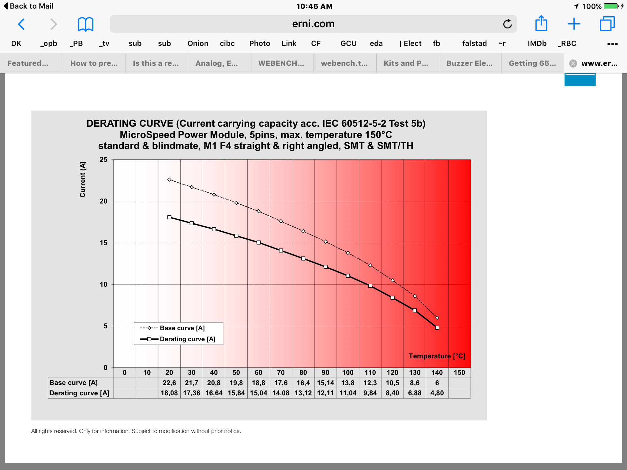
Thanks, but the following blade connector in the ERNI.com (part number = 214550) connector are said to be able to do 12 Amps per contact at 85degC....So thats 60 Amps for the whole connector...

ERNI.com part number 214550.....

**broken link removed**
 

Blade connector with 12A per contact at 85degC?

Hello,
The ERNI.com connector (part number 214550) has a catalog page stating current capability per contact is between 3.4A and 5A at 85degC.
However, we have been told that they are good for 12 Amps per contact at 85degC and wish to use them for that. Is this ok?

ERNI.com connector (Part number = 214550)

https://www.erni.com/en/products/show/product/214550/
 

If you put a round pin in a round socket, the point of contact is at most a line. If the pin or the socket is split (into two), the actual contact can become two lines (assume some spring action). For a flat blade contact, the actual region of contact can increase to be a small area (rather than a point or line). Therefore always prefer flat blade contacts (rather than round pin connections)- they will offer better contacts. The self-cleaning action of the blade contacts are somewhat better (my opinion) when you compare with a round contact.
 

Re: Blade connector with 12A per contact at 85degC?

Lots of ambiguity there, datasheet says one thing, derating curve says something totally different.

I would go with the datasheet values, which would make this a gross overload, better to err on the safe side. Even if the derating curve is correct (And I suspect the supplied one is for the wrong connector) you would be painfully close to the 150 degrees thermal limit and that is never a good place to be, only place you want electronics that hot is down hole, and that is a whole other thing.

End of the day you are the engineer signing off on this thing, would you be happy using any part at >200% of datasheet maximum? I know I wouldn't!

Regards, Dan.
 
  • Like
Reactions: treez

    T

    Points: 2
    Helpful Answer Positive Rating
Depends, there are some very heavy current round contacts that use a beryllium copper helical spring sleeve as part of the socket assembly, from maybe 60 up to a 1,000A or so for traction power and the like.

Not cheap, but nothing at that current level is.

These are a variation commonly used in the touring show and temporary power industry https://www.ittcannon.com/p/549/powerlock/

Regards, Dan.
 
  • Like
Reactions: treez

    T

    Points: 2
    Helpful Answer Positive Rating
Probably cost you an arm, leg, kidney, eye, ear, lung, and indentured servitude of the next 3 generations of your family to buy one. ;-)

Indeed!
This phrase says it all:............TE’s Snap-Lug power connectors are used in military ground vehicles, commercial aviation
 

Could be worse, it could mention that scariest of phrases "Space Qualified"....

Regards, Dan.
 

You need the mill-volt drop rating for the connector you want to use, to see how much voltage you will drop. You also need the specification for how many times you can plug and unplug the connector and hold this specification.

At this point i think what we have been discussing here may be unrealistic. The voltage drop at 65A will be to large compared to the 1V5 unless you want to spend a ridiculous amount of money.

I think a more realistic approach may be to use a cheaper connector and run a sense lead to the powered device, auto correcting any voltage drop.

You may also want to scrap the connector idea altogether. What about several/many wires soldered directly to the PCB and terminated with something your customer wants to use.
 

I think a more realistic approach may be to use a cheaper connector and run a sense lead to the powered device, auto correcting any voltage drop.

The concept of local regulation at the point of use is really very relevant here because the rather low voltage (1V5) is rather tough to regulate over a number of circuits.

It is your design and your philosophy but I believe best results can be obtained if you decide to regulate the voltage locally as and when needed. This improves reliability significantly at the cost of slight increase of complexity.
 

I think if you have to use a connector this would be my choice.

Digikey
Product Index > Connectors, Interconnects > Terminal Blocks - Barrier Blocks
In the "series" box select #8 Buchanan

This is a screw type terminal block with PC pins that has been used before time was time.
 

I agree the screw terminals will ensure thermal conduction for reliable performance with a long screw and parallel wire connections with a rugged style.

Considering it is only a 100W power supply, you can afford to lose 5 to 10 Watts in the connectors and wire of you monitor the voltage remotely and compute load regulation this way. I let you decide what to choose for a design spec, but you must choose one so it can be verified .
3390669600_1473347889.png

There is more data on the blade style, for yours.
FWIW
 
  • Like
Reactions: treez

    T

    Points: 2
    Helpful Answer Positive Rating
Status
Not open for further replies.

Part and Inventory Search

Welcome to EDABoard.com

Sponsor

Back
Top