Continue to Site

Welcome to EDAboard.com

Welcome to our site! EDAboard.com is an international Electronics Discussion Forum focused on EDA software, circuits, schematics, books, theory, papers, asic, pld, 8051, DSP, Network, RF, Analog Design, PCB, Service Manuals... and a whole lot more! To participate you need to register. Registration is free. Click here to register now.

Ground plane, patch, feedline dimesnion and the impedance matching

Status
Not open for further replies.

peteryuan

Newbie level 3
Joined
Jul 20, 2015
Messages
3
Helped
0
Reputation
0
Reaction score
0
Trophy points
1
Activity points
20
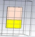
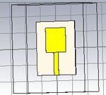
I am design a micro strip patch antenna for UWB application (3.1-10.6GHz) in CST.
The substrate is Rogers RT 5880 and the feedline, patch and ground plane is Copper (Annealed).
The feedline is Micro Line Feed.

the is result for S-parameter is accepted but the z-matrix(impedance) is around 40ohms

but my minimum tolerance is at least 0.5mm and the impedance is 50 ohms.

How & what is the dimension of the thickness of the patch, feed line and ground plane for that specification as mention above?

What other improvement can be made?
 

Attachments

  • uwb back.JPG
    uwb back.JPG
    17.4 KB · Views: 70
  • uwb front.JPG
    uwb front.JPG
    16.9 KB · Views: 67

Hi,

I suggest the following:

To have a realistic thickness for your patch, feed line & gnd plane, consider 1 oz of copper (~1,4 mils or 0.034 mm approximately). These numbers depend upon what thickness do you specify to the PCB manufacturer while manufacturing this design. I usually use 1 oz of copper in my pcb designs.

I am not sure on this end, but you can make the ground spread out on the complete board dimension on the bottom layer. Currently I see you have it only below the feed line. Also I think you can consider the feed line as a microstrip and use any of the online microstrip calculators to decide upon the feed line's width to match the 50 ohm impedance of your patch.

I hope this helps to improve your design.
 
the white is the substrate which is between the feed and the ground.
they all are just above the substrate.

the result from cst and the microstrip calcluator
 

Status
Not open for further replies.

Part and Inventory Search

Welcome to EDABoard.com

Sponsor

Back
Top