Continue to Site

Welcome to EDAboard.com

Welcome to our site! EDAboard.com is an international Electronics Discussion Forum focused on EDA software, circuits, schematics, books, theory, papers, asic, pld, 8051, DSP, Network, RF, Analog Design, PCB, Service Manuals... and a whole lot more! To participate you need to register. Registration is free. Click here to register now.

Dipole current distribution and Zin

Status
Not open for further replies.

kavea

Junior Member level 3
Joined
Apr 27, 2014
Messages
25
Helped
1
Reputation
2
Reaction score
1
Trophy points
3
Activity points
131
Hi guys,
Can someone tell me why at the resonance current and voltage distributions are shifted by 90deg from each other, while input impedance is purely real which means I and U in phase ?
 

Yes that is contradictory, but that is what we see everywere! A theoretic Wv/2 dipole have nearly Rin=73 Ohms and Xin=0 at the resonance (zero tickness, lossless), but current distribution with maximum at the middle and zeros at the ends and voltage with maximums at the ends and zero at the middle have 90deg shift from each other. How can it be Xin=0 and 90deg shift at the same time ??
 

Two different things - Amplitude vs. time and amplitude vs. location.

Amplitude vs. location:
The maximum current amplitude is always at the middle (feed) of the dipole, and current is zero at the open end, at any time. The max. voltage amplitude is always at the end of the dipole, and min voltage at the middle (feed), at any time.

Amplitude vs. time
At the feed, in the middle of the dipole, the voltage/current ratio is real (phase = 0).

Thank you, but i struggle to visualize it. Impedance can be defined at any location of antenna or only at its feed ?
 
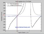
Note that for very small dipole antennas, the input impedance is capacitive, which means the impedance is dominated by a negative reactance value (and a relatively small real impedance or resistance).

As the dipole gets larger, the input resistance increases, along with the reactance.

At slightly less than 0.5 the antenna has zero imaginary component to the impedance (reactance X=0), and the antenna is said to be resonant.

dipole.jpg
 

Impedance can be defined at any location of antenna or only at its feed ?

The relevant impedance is measured at the feed, in the middle between the antenna wires.
If you measure at other locations, you would get other results.
 

2SunnySkyguy
Yes i know that

2volker@muehlhaus
Ok , is there any way to find this impedance at other locations ?

For example is there any logical explication for the value of current at 15th segment of this monopole ? (how NEC calculated it)
By the way, at the resonance, phase seems to be pretty constant along the antenna..
2014-05-13 20_06_36-Main [V5.8.14]  (F2).png
 

Since each Pole is a 1/4 wave, impedance is inverted at the tip , so impedance will be very high but still no reactance at resonance and you can interpolate (somehow) in theory from feed to tip. But why bother?
 

2SunnySkyguy
I finally understood the link between two voltage/current distributions (standing wave distribution and time distribution). But i would like to know how NEC calculates standing current at any location, i find it interresting. I thought about this formula to determine impedance at a distance l from a known one (feed), but it doesn't works because of unknown Zc
Code:
Zl=Zc*(Zl+j*Zc*tan(beta*l))/(Zc+j*Zl*tan(beta*l))
 

but it doesn't works because of unknown Zc
Code:
Zl=Zc*(Zl+j*Zc*tan(beta*l))/(Zc+j*Zl*tan(beta*l))

It doesn't work because this is for a transmission line with no radiation.
The equation can't be applied to antenna wires.

NEC divides the antenna into segments, and can calculate the current and voltage at the connection between segments. But this value is not really relevant for the user.
 

Status
Not open for further replies.

Part and Inventory Search

Welcome to EDABoard.com

Sponsor

Back
Top