Continue to Site

Welcome to EDAboard.com

Welcome to our site! EDAboard.com is an international Electronics Discussion Forum focused on EDA software, circuits, schematics, books, theory, papers, asic, pld, 8051, DSP, Network, RF, Analog Design, PCB, Service Manuals... and a whole lot more! To participate you need to register. Registration is free. Click here to register now.

Pic18f4520 project base help

Status
Not open for further replies.

KhaledOsmani

Full Member level 6
Joined
May 4, 2014
Messages
384
Helped
1
Reputation
2
Reaction score
1
Trophy points
18
Activity points
3,933
Hello dears,

This website is such a magnificent job. Great effort, in a smart way with interactions of great experienced members.

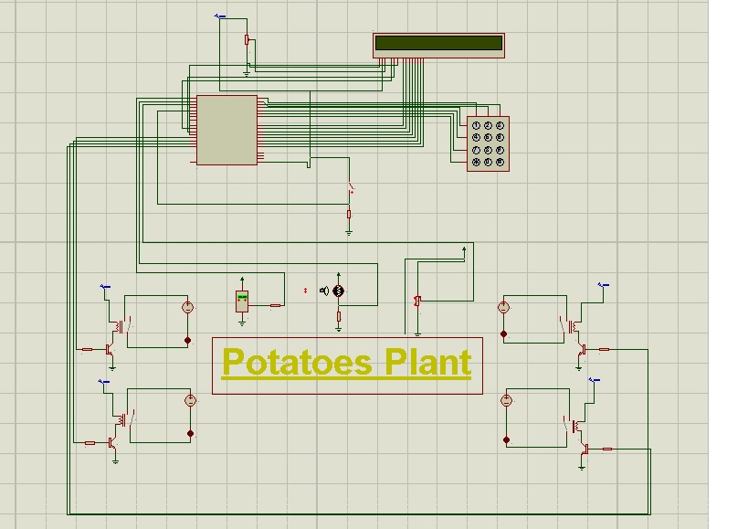
I`m doing a small project, concerning automation/control/monitoring about a green-house.
I`m using a PIC18F4520.
I`m coding in Assembly.
I'm using as output an 2*40 LCD (LMB402CFC): as an interface for the user.

The questions are as follows:
*What does the output of square blocks sequence on the LCD means? solutions?
*At first attempt the circuit ran good, but I made small changes in connections (no Short Circuit) And noticed on the oscilloscope a very high amperage (I = 0.8A) for 5V DC for the PIC and the LCD. Why?
*How sensitive a microcontroller is, and for how much I must be careful with it (beside temperature storage)?

Thanks,
 

1) Those square blocks indicate that you are not sending correct data to the LCD (or are not sending it correctly). Unless you are INTENDING to display blocks.
2) It sounds like something failed.
3) You have to be aware of static or overvoltage
 

Hi,

+1 to barrys entry

0.8A means a massive short.

Do you have the backlight connected and have you used a dropper resistor, the b/l leds are usually 4.2v max

A lcd typically takes 7 to 10ma and the backlight about 50ma+ if used.

What were your "small changes" ?

Normally Pics are quiet robust but some folk are more prone to static than others, so if in doubt use a proper wrist ground strap which includes a safety resistor.

LCDs can just go like that, the slightest short / wrong connection / bit of static can blow them, but some lcds just seem bomb proof


If after you sort your short out, things still do not work, if you want to post your circuit diagram and program code I can test it on my board as I also use the 4520 /Assembler for greenhouse controllers.

Always save versions your program code as you develop it, so you can always return to a previous condition if things go wrong.
 

Hello,

What do you mean by "Dropper Resistor" ??
As for the circuit Diagram, it ran very good via ISIS - Proteus.


More over, what resistor should be connected with a Light Dependant Resistor LDR, to make the light level as input to the PIC, accurately?

What about the LM35 (Temperature sensor) what resistor should be connected with, to make accurate values.


If ADC process is correctly made in the code, decimal value would take place on the LCD, with actual current values, or something else should be done?


thanks,
 

Hi,

Many lcds have backlight leds that run at 4.2v maximum so a 'dropper' resistor is often needed to reduce the 5v to 4.2v

Looking at the datasheet of your lcd, seems it has the dropper resistors fitted internally, so you can run them directly from +5v. Though you can always add a dropper resistor if you want to reduce the intensity of the leds.

As for a LDR it depends on the device you use, but typically a 10k trimmer is used to allow adjustment.

For how to use the LM35 just search this forum for the many posts on that device.
However perhaps look at sensors like the lo cost DHT11 , DHT22 or the more accurate and expensive SHT11 range of temperature and combined humidity sensors which are needed for greenhouse control.

Once your ADC values have been produced they many need some additional work to produce a meaningful result from the 1024 ADC steps.

Once you have a useful result then that value needs to be converted into ASCII for displaying on the lcd.

You can get a variety of routines from here to produce the desired result.
This example will take your 10 bit result and produce decimal output.
http://www.piclist.com/techref/A2DCodeGenerator.asp?bits=10&ref=5
 
Thank you wp100, you are an expert.
The project is running great now.
LCD & Keypad are connected and functioning.

As for the inputs: LDR, LM35, and soil moisture sensor:
LDR: connect a 10k trimmer: DONE
LM35: what resistor should I connect for optimum value (Note: I had tried to search for it, but every circuit has its own characteristics, so I cannot use one of the shown values; hence there must be a manufacturer suggested resistor to connect with)
Soil moisture sensor: I won't use any Arduino-based sensors, my project should only be written in assembly, I cannot use more than ONE processor.

As for the power supply, how can I get an exact 5V DC? There are no batteries manufactured for 5V (Why?) I also tried to use a voltage regulator: 7805, BUT still gives on the output an exceeding value of 5V (5.7V) which can blow the entire circuit up. How to have pure 5V DC to supply the circuit with?

here is a general overview of the circuit:
 

Status
Not open for further replies.

Similar threads

Part and Inventory Search

Welcome to EDABoard.com

Sponsor

Back
Top