Continue to Site

Welcome to EDAboard.com

Welcome to our site! EDAboard.com is an international Electronics Discussion Forum focused on EDA software, circuits, schematics, books, theory, papers, asic, pld, 8051, DSP, Network, RF, Analog Design, PCB, Service Manuals... and a whole lot more! To participate you need to register. Registration is free. Click here to register now.

Analysis of S(1,1) dips in LC Low-Pass Filter circuit.

Status
Not open for further replies.

cannibol_90

Member level 5
Joined
Jun 20, 2009
Messages
83
Helped
5
Reputation
10
Reaction score
5
Trophy points
1,288
Activity points
2,066
Hi,

First of all, I hope everyone's fine!

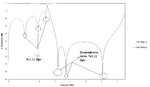
I am trying to implement elliptic filters using lumped elements and have been successful in designing one. The images below shows the circuit diagram and response of a 7th order elliptic Low-Pass filter.


7th order elliptic filter.jpg


Now, one can easily find out the frequencies of the transmission zeros by evaluating the resonant frequencies of the parallel LC circuit.

Now, my questions are as follows;

1. How can one find out the frequencies corresponding to the S(1,1) dips from the lumped (LC) elements?

2. What does it mean when there is a frequency shift in the S(1,1) dips?

3. Also, what does it mean when one of the S(1,1) dips are missing? How can I bring it back to the original value/frequency, i.e. how can I adjust the L,C values to obtain the original plot?

Can someone help me? PLEASE!!!
 

Attachments

  • 7th order elliptic filter circuit simulation.bmp
    1.5 MB · Views: 111
  • 7th order elliptic filter circuit simulation.JPG
    7th order elliptic filter circuit simulation.JPG
    36.8 KB · Views: 205
Last edited:

You have 3 notches and you will have also 3 Transfer zeros in Transfer Function consequently 3 notches in Input Impedance Function while the output is terminated.
First Zero=3.3362E9 Hz
Second Zero=2.89035E9 Hz
Third Zero=5.26663E9 Hz
These zeros are seen on your graph coming from notch circuits but hey are also shifted because of parallel capacitors.
You can say the same thing for S11 zeros.If you are able to compute the Input Impedance, you will see the exact impedance function zeros as well.
 
  • Like
Reactions: cannibol_90

    V

    Points: 2
    Helpful Answer Positive Rating

    cannibol_90

    Points: 2
    Helpful Answer Positive Rating
The resonant frequency of a series parallel L-C circuit is f=1/(2*PI*sqrt(L*C)). Some of your S11 dips are due to these poles. Others are due to the series L/shunt C pole. The poles will move around for many reasons.

Some Reasons Filter Response/S11 Dips Move Around
1. Variations in component values. Most surface mount components that you buy have a bi-modal distribution since the companies that make surface mount components charge more for tight tolerance parts and they take them out and sell you the rest. This sometimes makes your filter behave unexpectedly.

2. Magnetic coupling between inductors. This usually causes unexpected results in your filter. Higher than expected losses would be seen. Try putting inductors at 90 degrees to each other or far enough away to reduce magnetic coupling. You can also see frequency shifts due to magnetic coupling. This is very difficult to model since you don't know the orientation of the coils in the inductor beforehand. Try flipping the inductor and see if you can change the response of your filter. There is usually an orientation mark on surface mount inductors.

3. Ground inductance. If your board thickness is big and your filter frequency is high then the parasitic inductance of the component itself and of the GND via can cause a downshift in your filter response. You may need to adjust your shunt capacitors lower in value to compensate for this parasitic inductance.

Hope this helps with your design.
 
  • Like
Reactions: cannibol_90

    V

    Points: 2
    Helpful Answer Positive Rating

    cannibol_90

    Points: 2
    Helpful Answer Positive Rating
You have 3 notches and you will have also 3 Transfer zeros in Transfer Function consequently 3 notches in Input Impedance Function while the output is terminated.

These zeros are seen on your graph coming from notch circuits but hey are also shifted because of parallel capacitors.

If you are able to compute the Input Impedance, you will see the exact impedance function zeros as well.

1. The parallel capacitors (to the ground) seem to shift only the attenuations zeros (S11 dips). They don't shift the transmission zeros. Yes, the parallel capacitors (in series with the transmission line) shifts the transmission zeros (obviously they need to), but they also shift the S11 dips too. The circuit and its response shown below proofs my observation.

elliptic filter 7th order C values changed.jpg

elliptic filter 7th order C values changed response.jpg

2. Can you please tell me the exact mathematical procedure to calculate the input impedance for the impedance function zeros?

3. Also, I am trying to implement the above circuit using microwave implementation (Stepped impedance, Open Circuited Stubs et al.). So, what should I be careful of? How to get the most approximate/accurate response for the lumped element circuit implemented?

I am an amateur, so please help me.
 

Before going in a deep mathematical analysis is good to follow a tip/rule when designing multi-pole elliptical filters. Try to avoid using shunt caps or shunt inductors at input/output ports.
I know, most of the filter simulators do not provide this option in auto-design mode, so you have to do it manual.
Compared to other filter types, elliptical (Cauer) filters are more sensitive to components tolerances, but avoiding using shunt elements at input/output ports minimize somehow this issue.
This was recommended to me by an old RF guy which designed elliptical filters in 60'ies using just formulas and an old slide ruler calculator, and of course, a lot of experiments.
 
1. The parallel capacitors (to the ground) seem to shift only the attenuations zeros (S11 dips). They don't shift the transmission zeros. Yes, the parallel capacitors (in series with the transmission line) shifts the transmission zeros (obviously they need to), but they also shift the S11 dips too. The circuit and its response shown below proofs my observation.

View attachment 102222

View attachment 102223

2. Can you please tell me the exact mathematical procedure to calculate the input impedance for the impedance function zeros?

3. Also, I am trying to implement the above circuit using microwave implementation (Stepped impedance, Open Circuited Stubs et al.). So, what should I be careful of? How to get the most approximate/accurate response for the lumped element circuit implemented?

I am an amateur, so please help me.
The exact mathematical calculation of the Input Impedance is pretty difficult ( I have tried for two sections, it was quite hard to do without make error) by hand.But there are some Filter Handbooks who explain how to do it. MatLab may also be used.
For microwave implementation is not extremely difficult ( easier than calculate ), there are some filter programs,simulation softwares even some applets to calculate the physical elements of your filter.
Don't worry about transmission and reflection zeros because the main specifications are not them.The essentials of implementation of a filter are 3dB Cut-off frequency corner,Stop-band Attenuation@offset ,Insertion Loss,Return Loss,Pass-band Ripples, etc.
Transmission zeros are particularly used to suppress certain frequencies and for this purpose zero-shifting technique is rarely used but it's not your case.
First, you should define essential specs.of your LP.
 
  • Like
Reactions: cannibol_90

    V

    Points: 2
    Helpful Answer Positive Rating

    cannibol_90

    Points: 2
    Helpful Answer Positive Rating
The resonant frequency of a series parallel L-C circuit is f=1/(2*PI*sqrt(L*C)). Some of your S11 dips are due to these poles. Others are due to the series L/shunt C pole. The poles will move around for many reasons.

Some Reasons Filter Response/S11 Dips Move Around
1. Variations in component values. Most surface mount components that you buy have a bi-modal distribution since the companies that make surface mount components charge more for tight tolerance parts and they take them out and sell you the rest. This sometimes makes your filter behave unexpectedly.

2. Magnetic coupling between inductors. This usually causes unexpected results in your filter. Higher than expected losses would be seen. Try putting inductors at 90 degrees to each other or far enough away to reduce magnetic coupling. You can also see frequency shifts due to magnetic coupling. This is very difficult to model since you don't know the orientation of the coils in the inductor beforehand. Try flipping the inductor and see if you can change the response of your filter. There is usually an orientation mark on surface mount inductors.

3. Ground inductance. If your board thickness is big and your filter frequency is high then the parasitic inductance of the component itself and of the GND via can cause a downshift in your filter response. You may need to adjust your shunt capacitors lower in value to compensate for this parasitic inductance.

Hope this helps with your design.

1. What is a bi-modal distribution? Well, I will be designing the parallel LC circuits using DGS(s) (Defected Ground Structure). What should I be careful of using DGS?

2. Well, I believe magnetic coupling is going to take an important part in my filter design. After designing my circuit using HFSS, I will update the results.

3. Does this mean, I have to adjust both the DGS as well as the shunt capacitor values to obtain an appropriate design? My substrate thickness is going to be 1.6mm and the range of frequency that I will be working on will be from 0.6 GHz to 10 GHz.

- - - Updated - - -

Before going in a deep mathematical analysis is good to follow a tip/rule when designing multi-pole elliptical filters. Try to avoid using shunt caps or shunt inductors at input/output ports.
I know, most of the filter simulators do not provide this option in auto-design mode, so you have to do it manual.
Compared to other filter types, elliptical (Cauer) filters are more sensitive to components tolerances, but avoiding using shunt elements at input/output ports minimize somehow this issue.
This was recommended to me by an old RF guy which designed elliptical filters in 60'ies using just formulas and an old slide ruler calculator, and of course, a lot of experiments.

Wow! That's a nice piece of information. But, as you can see, I have shunt capacitors both at the input as well as the output ports. This forms the elliptical filter design.

Now, how to reduce the effect of it being involved? I will be using methods such as Richard's Transformation or Stepped Impedance for its microwave implementation and HFSS EM simulation software.

- - - Updated - - -

The exact mathematical calculation of the Input Impedance is pretty difficult ( I have tried for two sections, it was quite hard to do without make error) by hand.But there are some Filter Handbooks who explain how to do it. MatLab may also be used.
For microwave implementation is not extremely difficult ( easier than calculate ), there are some filter programs,simulation softwares even some applets to calculate the physical elements of your filter.
Don't worry about transmission and reflection zeros because the main specifications are not them.The essentials of implementation of a filter are 3dB Cut-off frequency corner,Stop-band Attenuation@offset ,Insertion Loss,Return Loss,Pass-band Ripples, etc.
Transmission zeros are particularly used to suppress certain frequencies and for this purpose zero-shifting technique is rarely used but it's not your case.
First, you should define essential specs.of your LP.

Of course, the filter specifications are:-

1. Order = 7.
2. Cut-off frequency = 2.5GHz.
3. Minimum attenuation in the Stop-band = 55 dB.
4. Maximum attenuation in the Pass-band = 0.177dB.
5. Sharpness Factor = 1.2.
 
Last edited:

BTW, from a practical point of view, not too many people use the filter topology that you show. Most would use the Dual of that circuit, where the elliptical poles are formed by series connected L-C in shunt, and series L in between. If you try to layout your filter, and try to compensate for board parasitics, the reason will become obvious.
 
Status
Not open for further replies.

Part and Inventory Search

Welcome to EDABoard.com

Sponsor

Back
Top