Continue to Site

Welcome to EDAboard.com

Welcome to our site! EDAboard.com is an international Electronics Discussion Forum focused on EDA software, circuits, schematics, books, theory, papers, asic, pld, 8051, DSP, Network, RF, Analog Design, PCB, Service Manuals... and a whole lot more! To participate you need to register. Registration is free. Click here to register now.

Hysteretic Buck converter circuitry?

Status
Not open for further replies.
T

treez

Guest
Hello,
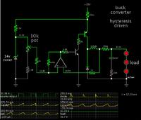
The below is the schematic of my attempt at doing a simulation of a hysteretic buck converter.(LED driver)

The idea is that one comparator will turn off the FET when the inductor current reaches the peak, and the other comparator will turn the FET ON when the inductor current reaches the trough.
However, unfortunately, it doesn't work, as a little "glue" logic is needed, and I haven't quite got this right yet.

Do you know how I can make this work?

schematic and LTspice simulation attached
 

Attachments

  • Hysteretic buck.pdf
    22.3 KB · Views: 111
  • Hysteretic buck.txt
    8.1 KB · Views: 58

Thanks, but I doubt a Schmitt trigger will do it.
I need some way to make the 0.2V ref comparator switch the fet on and simulataneously disable the 0.3v ref comparator at the same time....and then vice versa, so that the inductor current bangs up and down between the two comparator references.
 

A diode load has a tendency to disturb the sensing method. The PN volt threshold may be low, and your reference voltage may be high. The converter may try to remain in the switch-On part of the cycle indefinitely.

In addition your sense voltage needs to swing within a range so as to sustain hysteresis.

I recommend that you try inserting a resistor (say 100 ohms) in series with your led's.
 
  • Like
Reactions: treez

    T

    Points: 2
    Helpful Answer Positive Rating
In addition your sense voltage needs to swing within a range so as to sustain hysteresis.

the sensed voltage will bang up and down between the upper and lower comparator refs.


Here is a fairly working version, but it is noisy, with sometimes uneven switching.
Do you know how to get rid of the noise in this new circuit below? (otherwise it works quite well)
The comparators have "L" inputs which latch their output.

Simulation and schematic attached
 

Attachments

  • Hysteretic buck2.pdf
    21.2 KB · Views: 78
  • Hysteretic buck2.txt
    7.3 KB · Views: 60
Last edited by a moderator:

the sensed voltage will bang up and down between the upper and lower comparator refs.

----------------------------------------

Here is a fairly working version, but it is noisy, with sometimes uneven switching.
Do you know how to get rid of the noise in this new circuit below? (otherwise it works quite well)
The comparators have "L" inputs which latch their output.

Simulation and schematic attached

This sounds like 'hiccup' mode.

Normally current pulses are equal. Cycles are regular.

However it appears you have either (a) non-regular switching, and/or (b) non-regular current pulses.

Your schematic shows your sense wire is connected on the opposite end of the coil from the load. Feedback is 'loose'.
Your hysteresis delivers a strong pulse one moment, and a weak pulse the next.

I believe your feedback would be tighter if you were to put the sense wire at the load.

Simulation of a hysteresis-driven buck converter, controlled by an op amp.


Notice the sense wire is located near the load and smoothing capacitor.

Here is the reason it is easier to use a resistive load in the experimental phase.
With a diode load, the voltage difference between On and Off is only a few tenths of a volt. The diodes will gobble any overvoltage immediately. And the smoothing capacitor stops discharging through the diodes after they turn off.
For this reason, the reference voltage needs to be very close to the load voltage. Otherwise the buck converter does not operate.
 
  • Like
Reactions: treez

    T

    Points: 2
    Helpful Answer Positive Rating
ok thanks.
I don't usually think of this as hiccup mode...hiccup mode is where a faulted controller continually retires, is it not?
Anyway, thanks for your schem.
However, I am trying to do a controller like the zxld1366 whereby the peak and trough of the inductor current are exactly defined by the comparators no matter what is the input voltage or output voltage.
 

Both circuits have the same problem, the gate current peaks are disturbing the measurement due to unsuitable shunt connection.

Apart from this problem, the part count is rather high related to the essentially simple circuit function. The circuit seems far away from a real design.
 
  • Like
Reactions: treez

    T

    Points: 2
    Helpful Answer Positive Rating
it is too complicated, but its the simplest two comparator hysteretic converter that I can come up with.
Two comparators are needed to give improved output current accuracy with changes in vin and vout.
When each comparator trips, it needs to latch itself, and unlatch the other comparator....so it needs the extra circuitry.

I am not sure which "shunt" you mean?.

I think that the problem is something to do with the interval in which the comparators are latched..but i'm not sure.
I cant see the gate current causing a problem?..there is a current sense filter.
 

I am not sure which "shunt" you mean?.
Of course the shunt responsible for current measurement, R1. Unfortunately the driver supply ground is connected to the right side of the shunt, so the gate currents are running through it. You know if you watched the simulation waveforms thoroughly.
 
  • Like
Reactions: treez

    T

    Points: 2
    Helpful Answer Positive Rating
I see what you mean, but that is how sense resistors get connected in flybacks, boosts, etc , and they aren't noisy.
 

but that is how sense resistors get connected in flybacks, boosts, etc , and they aren't noisy.
They don't use a 100A FET for a 1.5A switcher. And it's easy to connect the shunt differently, measuring only the inductor current.
 
  • Like
Reactions: treez

    T

    Points: 2
    Helpful Answer Positive Rating
ok I will try that....incidentally, making "max timestep " equal 100ns solves the problem, -I don't know why.
 

If you can't avoid switching transients being detected by your current comparators, you need to block these transients in threshold evaluation, e.g. by introducing a minimum pulse width.
 
  • Like
Reactions: treez

    T

    Points: 2
    Helpful Answer Positive Rating
Status
Not open for further replies.

Similar threads

Part and Inventory Search

Welcome to EDABoard.com

Sponsor

Back
Top