Continue to Site

Welcome to EDAboard.com

Welcome to our site! EDAboard.com is an international Electronics Discussion Forum focused on EDA software, circuits, schematics, books, theory, papers, asic, pld, 8051, DSP, Network, RF, Analog Design, PCB, Service Manuals... and a whole lot more! To participate you need to register. Registration is free. Click here to register now.

help for full bridge topology

Status
Not open for further replies.

deepakchikane

Full Member level 3
Joined
Jul 17, 2012
Messages
178
Helped
2
Reputation
4
Reaction score
2
Trophy points
1,298
Location
Mumbai, Maharashtra, India, India
Activity points
2,623
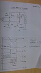
can anyone guide me in designing full bridge topology (replaced bridge rectifier with full bridge mosfet)

conditions: i/p=230vac @ 6amp

frequency=50hz & for another 10 khz (1 leg)

frequency=50hz & for another 10 khz (2 leg)

i have designed for 50hz with the help of op-amps & push pull amplifier.

i am having problems with the grounds.

will be there any tips for pulse transformer.(i am designing trafo first time)..??

will be differential amplifier can work to seperate ground (i did exp but again gnd problems)

please help me out
 

the billings and morey book is the only book in the world which gives a good explanation of the current transformer design....did you mean that..(the current transformer that you need for sensing the primary current in current mode control)
 

May be it's me, but I'm unable to hear a clear question from the original post. And there's no reference to current transformers.
 
  • Like
Reactions: treez

    T

    Points: 2
    Helpful Answer Positive Rating
OK I see your point....."pulse trxfmr" must mean the high side driver transformer....in any case, knowledge of cx txfmr will be useful I hope.?

Pulse txfmr.....I would do it by having a high side fet driver, and the pulse txfmr would pulse into the fet driver input....the pulse txfmr also supplies the vcc to the high side fet driver.
 

May be it's me, but I'm unable to hear a clear question from the original post. And there's no reference to current transformers.
fvm:
pls see attachements

M3 & M4 are the mosfet (transistor technology)-GeneSic GA06jt12-247 (driving by 10khz)

M1 & M2 Are irf 730 (driving by 50hz)

also tell me
calculation for the mosfet gate drive for both
 

Attachments

  • DSC_0193.jpg
    DSC_0193.jpg
    805.5 KB · Views: 117
  • Like
Reactions: treez

    T

    Points: 2
    Helpful Answer Positive Rating
The intended circuit purpose and operation is unclear.

Did you notice that the MOSFET body diodes will always conduct in the quadrants I and III. The MOSFET switches give only a controllability in quadrants II and IV, when the input current has opposite direction to input voltage and instantaneous energy flow is from load to AC source.

fvm:
i drive the above full bridge (on 50hz)
it worked smooth..

now i am replacing bottom mosfet with higher frequency.

as the body diode conducts (take f/b from d-s) n give it to the driver of that mosfet.
then mosfet will be triggered by gate drive.

yess m also confusing in the fact for whether it is flowing from drain-source or source-drain..??

but expriment shows that it can flow through source-drain as well..
 

Status
Not open for further replies.

Similar threads

Part and Inventory Search

Welcome to EDABoard.com

Sponsor

Back
Top