Continue to Site

Welcome to EDAboard.com

Welcome to our site! EDAboard.com is an international Electronics Discussion Forum focused on EDA software, circuits, schematics, books, theory, papers, asic, pld, 8051, DSP, Network, RF, Analog Design, PCB, Service Manuals... and a whole lot more! To participate you need to register. Registration is free. Click here to register now.

Sine-wave DC rectifier circuit formula

Status
Not open for further replies.

sh-eda

Member level 1
Joined
Oct 1, 2010
Messages
40
Helped
1
Reputation
2
Reaction score
1
Trophy points
1,288
Activity points
1,735
Hi,
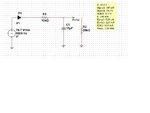
I wonder if someone could tell me if there is a formula I can use to work out what the DC voltage / average voltage will be in the circuit.
(A half way rectifier connected to resistor divider, and a smoothing capacitor on the output of a divider)
I think I should be able to work it out, or derive it, but I've forgotten how to do it and but it seems more complicated that it looks.
Maybe its really simple, but I know it's not as simple as Vpk/pi.
Appreciate any help
Thanks

- - - Updated - - -

Sorry I think I have posted this in the wrong forum..
 

Attachments

  • rectifier.jpg
    rectifier.jpg
    84.6 KB · Views: 113

A year or so ago, I researched this very subject, and read all of the scientific papers I could find about it, all the way back to the 1940s (I had full IEEE access at the time.).

It turns out to be "surprisingly complex", as many of the authors stated. And I agree.

It's not too difficult to get approximate equations. But there is no general closed-form solution. It always comes down to trying to solve for when the rising sinusoid of the input intersects the decaying exponential of the capacitor. And that is a transcendental equation with no closed-form solution.

By the way, your circuit wouldn't give you the right equation for a power supply that had your voltage source feeding a transformer, as it probably would be in many cases, because you also need to model at least the windings' leakage inductances and resistances, sine they can make the rectifier output go higher than the input voltage.

Anyway, ignoring that last problem for a moment, you can get equations that are very close to being accurate by using a trick or two. One good one is to use the Taylor Series expansion for either the input sinusoid or the exponential capacitor voltage, or both. Usually just the first term or two of the series is used and the expressions are then linear.

You still have a second-order differential equation when the rectifier is conducting (if you include leakage inductance of a transformer) and a first-order differential equation when the rectifier is not conducting. But at least you can get a close approximation of when to switch between the two. You could also assume that the output current is constant into an active DC load (e.g. an amplifier with a square wave signal), which automatically makes the cap voltage decay linearly, which helps.

In my case, I decided to go for an "exact" solution, using numerical techniques to solve the differential equations (and model the non-linear diode behavior). I wrote a VBA macro for MS Excel that did it, using a fourth-order Runge-Kutta algorithm to help solve the differential equations. Since I assumed a constant-current load (the worst case for an audio amplifier, with current equal to the peak, not RMS, current that a sine-wave output signal would have, AT THE RATED MAX POWER), I was able to derive exact closed-form equations for when the rectifier turned on and off. But that might only be possible for a numerical solution, because, during the numerical iterations, all of the derivatives are also available! (I have attached the short paper I wrote about it.)

if you are just trying to size the power supply components for an application, then it's much easier. All you really need to know is the maximum average or RMS load current, or the peak or RMS output voltage or current assuming a sinusoidal signal with an active load. And you need to know the AC Mains frequency.

Then you can start with the ideal capacitor equation,

i = C dv/dt

and then use an approximate version of it, like I gave in the post at

https://www.edaboard.com/threads/292663/ ,

but with the worst-case Δt set to

Δt = 1 / (2 fmains)

For certain types of active loads, you get free help in finding the constraints for the Δv (the max p-p ripple voltage). You might also have to modify the equation I gave, to account for your extra resistor.

Also, if your load is an amplifier, or a regulator, don't forget to account for the clipping or dropout voltage. For an amplifier, that would be the minimum voltage between the power rail connection and the output, which is typically between 2 and 6 volts (e.g. Vce_min + the voltage across a small emitter resistor). In that case, you'd have to use something like

Δv_max = Vrail_peak - Vclip - V_signal_peak

It's surprising how many people forget that the amplifier has to occupy some voltage space between the top of the signal peak and the bottom of the ripple voltage.

Also don't forget to account for the transformer regulation, and higher and lower than normal AC Mains voltages.

Edit: The next post reminded me that I forgot to say: I always advise everyone to simply use LT-Spice, or some other simulator, when designing or investigating a linear power supply circuit.

If you want to find the technical and scientific papers on how to write and solve the equations for your circuit, search for things like "uncontrolled single phase rectifier circuit equation*".

Cheers,

Tom

View attachment Analysis of an Uncontrolled Single-Phase Power Supply Rectifier Circuit - Gootee - dV9.pdf

View attachment Rated Maximum Output Power vs Reservoir Capacitance et al.doc
 
Last edited:
  • Like
Reactions: KerimF

    KerimF

    Points: 2
    Helpful Answer Positive Rating
The simple half-wave rectifier shown will charge the capacitor without load to 70Vrms x sqrt(2) = 100 V approx.
When you connect the load resistor, the voltage will drop to the resistor ratio 10k/(10k+20k) = 1/3, i.e. 66V.
 

The simple half-wave rectifier shown will charge the capacitor without load to 70Vrms x sqrt(2) = 100 V approx.

Right.

When you connect the load resistor, the voltage will drop to the resistor ratio 10k/(10k+20k) = 1/3, i.e. 66V.

Actually, since the time constant RC (10K//20K and 10uF) is relatively much longer than the period of 1 KHz of the voltage source, we can assume Vout is almost constant (in the steady state, with a low ripple). In this case, we have the equation:

Idc_r1 = Idc_r2 (absolute values)

But
Idc_r1 = [ Vpeak * SIN (a) - Vout * a ] / PI / R1
where:
a = ACOS ( Vout / Vpeak ) , in radian

And
Idc_r2 = Vout / R2

Therefore:

{ Vpeak * SIN [ ACOS ( Vout / Vpeak ) ] - Vout * ACOS ( Vout / Vpeak ) } / PI / R1 - Vout / R2 = 0

The simulator gives Vout (average) = 33.22 V


The numerical solution of the equation gives Vout equal to about 33.4 V for:
Vpeak = 100 - 0.7 = 99.3 V
R1 = 10 K
R2 = 20 K
 
Last edited:
  • Like
Reactions: tgootee and FvM

    FvM

    Points: 2
    Helpful Answer Positive Rating

    tgootee

    Points: 2
    Helpful Answer Positive Rating
Here is more math about the main equation related to R1:

Idc_r1 = Vdc_r1 / R1

But V_r1 is a sinewave tip:

V_r1 (x) = Vpeak * COS (x) - Vout , if -a ≦ x ≦ a where a = ACOS ( Vout / Vpeak )
V_r1 (x) = 0 otherwise

Vdc_r1 = 2 / (2*PI) * ∫ V_r1 (x) * dx from x=0 to x=a

Vdc_r1 = 1 / PI * [Vpeak * SIN (x) - Vout * x] , from x=0 to x=a

Vdc_r1 = 1 / PI * [Vpeak * SIN (a) - Vout * a]
 
Last edited:
Idc_r1 = Vdc_r1 / R1

But V_r1 is a sinewave tip:

V_r1 (x) = Vpeak * COS (x) - Vout , if -a ≦ x ≦ a where a = ACOS ( Vout / Vpeak )
V_r1 (x) = 0 otherwise

Vdc_r1 = 2 / (2*PI) * ∫ V_r1 (x) * dx from x=0 to x=a

Vdc_r1 = 1 / PI * [Vpeak * SIN (x) - Vout * x] , from x=0 to x=a

Vdc_r1 = 1 / PI * [Vpeak * SIN (a) - Vout * a]

Wonderful effort in math! Now build and test the real circuit to see who is right!
 

Thanks to all the answers, (sorry delayed response) I will go through them. Such a simple circuit is actually quite difficult, I thought it might be just me...
I generally use a simulator, Multisim or the Proteus, (the analogue devices version of Multisim is free).
I looked into lots of ways of doing this, but I couldn’t quite get it. I thought it would be a matter of integrating, but the charging and discharging periods (to integrate between)depend on the Voltage across the capacitor which you don’t know.
I did some excel spreadsheet calculations to try to work it out, i also worked it out for a squarewave (which is simple).
Thanks
 

Attachments

  • Rectifier excel.zip
    643.2 KB · Views: 112
  • Like
Reactions: KerimF

    KerimF

    Points: 2
    Helpful Answer Positive Rating
Such a simple circuit is actually quite difficult

It seems you didn't have time to read my previous posts (and of others) and know that the problem is solved ;)
 

I do not believe it has been solved, in the formal sense.

Finding the intercepts between the sine input voltage and the exponential capacitor voltage, which must appear somewhere in the solution, is a transcendental equation that has no closed-form solution.

And the start and end of a charging pulse (i.e. those intercepts) are not symmetrical about the peak of the input sine.

And it's no longer a sine, in between the intercepts, anyway.

Also, the diode is not ideal and has a non-linear resistance versus current or voltage.

And to really get fairly close to predicting the actual peak capacitor voltage, we would need to include the inductance and resistance of transformer windings, which often cause the capacitor voltage to peak higher than the transformer's nominal output voltage.
 

You are right tgootee, it wasn't a general/academic solution.

It is just a practical one, because in real life, sometimes using a simple equation to get an approximated answer is much better than no solution at all ;)

Please note that this relatively simple calculation was based on the assumption that the ripple on the capacitor is negligible. For the given circuit, it is just about 100 mVp-p that is about 0.3% of the average DC voltage. Of course, by decreasing the frequency or the capacitance to the point the ripple becomes relatively high, the error in the result will increase and we cannot get the minimum and maximum peaks of the ripple as well.

I don't expect I can convince you because I didn't learn the advantage of applying approximated solutions till I designed too many hundreds boards first, after graduation. In fact, at the university I was like you. I mean when I didn't have a calculator that had the constant PI, I used entering it as 3.1416 not 3.14 ;) Later, I discovered that the tolerances of some circuit components I had to use (and their sensitivity to temperature) likely exceed the inacurracies of most approximated results I worked on ;)

Anyway, you do well if you take advantage of the new calculus tools and derive formulas as accurate as possible.
 
Thanks, KerimF.

Sorry. Sometimes I tend to over-react to the literal meanings of things.

You actually don't need to convince me. I am an old guy, and understand fairly well that it's usually useless to even think about more than two or three digits of precision, in much of analog electronics (and probably everything else!), unless you absolutely have to of course.

When I was young and was getting my EE degree, in the late 1970s, I "knew it all", and was extremely proficient with higher mathematics. Alas, I let most of it rust away. But, over the last ten years or so, I have been trying to bring some of it back, along with some electronics knowledge and abilities. It has been very enjoyable and satisfying, at times.

Maybe I seem too serious about it, sometimes. I got fixated on calculating capacitor values for a long time, for example. But it was just very interesting, to me. And it seemed like there was not enough available information about it for hobbyists, such as the many people who like to try to design audio power amplifiers. First I got interested in how to calculate the required values and placement distances of decoupling capacitors, and then also PSU reservoir capacitors.

It's actually much more difficult to help someone get a home-made 2-sided PCB to work well than it is to get a professional multi-layer board to work well. So I have delved-into the equations for decoupling caps and the parasitic inductances (et al) of the power and ground traces, for low to medium speed circuits, for example.

One interesting problem that I have not seen solved elsewhere is the capacitance required to provide the current for a signal through a resistive load, for OTHER than a constant load current. For example, someone asked how the power supply reservoir capacitance value was related to the ability of their power amplifier to accurately re-produce bass (low frequencies), since basically all of the speaker current comes directly from the capacitors. So I derived equations relating sinusoidal signal frequency and available capacitance (and mains frequency, output power, etc).

I already had an upper-bound equation, that assumed a constant current at the peak sine level given by the rated max power output. But some people really do want to know the minimum required value (especially for production). It would only be valid for a single sine. But I decided that a single sine would be a good start and maybe it could even be combined with Fourier theory, later, to cover any signal type.

I was able to find the correct solution for the case where the signal frequency is greater than the AC mains frequency. But I didn't get it right for the case where the signal frequency is lower than the mains frequency.

I'll attach the write-up. Maybe you can solve Case 2? <grin!>

Check it out. I think you'll appreciate it, especially if you keep in mind that it was done by an old guy who had forgotten most of the math he learned more than three decades ago.

(Sorry, I had to convert the docx file to a doc file, to be able to upload it. It went from 78k to 1 MB because the equations had to be changed to un-editable images of equations.)

View attachment Reservoir Capacitance Requirements_gootee_v5_26MAR2013a.doc

Cheers,

Tom

- - - Updated - - -

P.S. I did not have Mathcad, back when I did that. I have acquired it, since then, mainly to work on an image texture-recognition problem that sparked my interest. (Maybe I should now take another stab at Case 2, mentioned in the post above...)

If you don't have Mathcad, I HIGHLY recommend it! I got Mathcad 15, with application packs, which is normally about $1500. But if you go to Amazon.com and buy "Essential Mathcad", by Brent Maxfield, you can get a full, non-expiring Mathcad 15 for about $45!!

The book includes a license key that enables the approximately-250 MB download of the software.

I think that the book is out of print but there were quite a few new copies left at amazon.com, a few months ago.
 
  • Like
Reactions: KerimF

    KerimF

    Points: 2
    Helpful Answer Positive Rating
Sorry Tom, because from your first posts, you sound to me much younger than I ;) I was wrong and thank you for clarifying the situation. I am 64.

It happened that my hobby in life was solving tough Math problems. For example, while my friends (boys and girls) had a good time in swimming pool, I was enjoying learning more tricks in calculus or alike ;) In fact, the process of thinking based on logic (not just in science... hence long story) is the sole real pleasure I have in life. I know this should sound weird but this is how I am made/created ;)

Of course with age, I had to put glasses and I had to have a chirurgical operation, about 2 decades ago, to replace the inner bone of my ear with a plastic piece to restore my quasi-normal hearing (the second ear is now out of service). Naturally, with time, my research hours (pleasant time) had to be decreased gradually from about 12 hours to 2 hours daily at best ;)

Thank you for sharing your work about the reservoir capacitance.
I saved your doc file and I will try studying it and see if I can add anything after getting the main ideas of the problem since I am new to it. All my works were about various kinds of controllers (for consumers and industrial) so I didn't work with audio power amplifiers (hence the optimum design of their supplies) besides learning them in theory.

Kerim

Note:
Scientifically speaking, I cannot get normally almost all the tools available to most parts in the world (free or paid). This became worse lately since we live a real war (my city is attacked and surrounded by an army of foreign mercenaries sent from more than 25 countries, the media calls them rebels). This is a long story. Even for my complex MCU programs (firmware), I had to write them in assembly language using a text editor and an old assembler on DOS to get their object files (no full debugg and simulation functions).


Added:
Did you have time to simulate your work for some conditions in the least?
I was able installing LTspice.
 
Last edited:
Kerim,

I was thinking, the whole time, that YOU were much younger than I am. But maybe that was because you could still do mathematics, well. <smile>

Your hobby and your mode of thinking are very admirable, in my estimation. I was and am somewhat similar. And some of the engineers I know have some similar types of tendencies.

I sometimes think that many of us are on the Asperger's Syndrome spectrum. I took an on-line test, for that, and the results were mixed, but with some strong characteristics of Asperger's in certain areas (about half of the tested areas).

Yes, in the capacitance paper, the parts of the math that I was able to generate correctly do give behavior that matches the LT-Spice results, exactly. It is noted in the paper. The part that I did not yet get right is the case when the amplifier output sine's frequency is less than the AC mains frequency. The problem is to find the worst-case voltage dip of the capacitors (actually, the global-minimum voltage), as they supply the current to drive the sine through the load resistance. I think it's basically just a problem of finding the worst phase angle relation between the signal and the mains, i.e. the worst-case alignment of the signal current-draw with the gap between charging-pulses. I assumed that it would be when the sine current's peak was centered in the gap between charging pulses. But that is incorrect. Actually, with LT-Spice, you can see when it happens. And if the signal and the AC mains frequencies are closer to each other, the period of the variation of the capacitor voltage fluctuations is longer, before the minimum capacitor voltage occurs. It's related to the frequency difference (between signal and mains). So if they are only 5 Hz apart, the maximum voltage dip (minimum capacitor voltage) might only occur at 5 Hz (or 10 Hz) rate, like a "beat tone" when tuning an instrument and it's almost (but not quite) in tune.

We would need to be able to predict the minimum supply voltage (i.e. bottom of ripple waveform), in order to be able to know when clipping would occur, so we can then calculate the minimum capacitance that prevents the voltage from falling below the value that would cause clipping to start.

I have been using LT-Spice for about ten years. For two or three years, I used it daily. It is a wonderful program. (A year or two ago, I finally did a deep dive into the .meas directives.) I hope that you are familiar with the LT-Spice users group, at yahoogroups.com . There are some great mathematicians, there, and much help, and great libraries and archives!

I just realized that you live in Syria. Please, keep your head DOWN!

What city are you in, there?

Highest regards,

Tom
 
  • Like
Reactions: KerimF

    KerimF

    Points: 2
    Helpful Answer Positive Rating
Hi Tom,

It is clear that you also enjoy the process of thinking not less than I do ;)

About the minimum capacitor voltage, I think, on these days, one has the advantage to live in both worlds; math and simulator.

By your work, one can get an approximated value of the smallest capacitor. Of course, he will likely have to select the first standard higher size.
Then, by modeling the circuit, he can start from the calculated value and test on the simulator the clipping at the load even by injecting a real audio signal (from a wav data for example).

Of course in both worlds, the modeling of elements has to reflect their real behavior. But the characteristics of the components that will be used on the real board may differ, for one reason or another, from what we expect them to be (as given by their datasheet in case they are genuine ones). It may be possible testing every crucial component and adjust accordingly its model on the simulator (and the values of its math symbols).

I believe that after working on this subject, for a certain time, mathematically and using a simulator with real tests if possible, one may find out one or more approximated, but practical, formulas that enable the designer choosing the optimum reservoir capacitor with minimum effort.

I am a member in LTspice group since a few years. But since about a year, I visit the group, only once a month at best, to find out what is new. Lately, I had to work on designs that could interest the local market only. These designs have relatively simple analog circuits driven by an MCU. So I use sometimes LTspice on these days just for answering some questions here in this group (using it as a verification tool or just a circuit drawing one).

For instance, did you have an interest in communications, anytime in the past? My MS thesis, in year 1979, was designing a rather simple, but reliable, DSB-SC (Double Sideband Suppressed Carrier) analog demodulator (not digital). It was a novel solution (I discovered it due to an error after about 5 months of failures) and it seems, even after 30 years, it is not known yet by all universities in the world ;) I used this simple low-cost demodulator for my private RF link about 30 years ago and for a few years only when I didn't have a phone line at house and I had to contact my shop... via a secure link ;)

I was born in Aleppo city where I live now.

Ultimate Regards ;)

Kerim
 

Status
Not open for further replies.

Similar threads

Part and Inventory Search

Welcome to EDABoard.com

Sponsor

Back
Top