Continue to Site

Welcome to EDAboard.com

Welcome to our site! EDAboard.com is an international Electronics Discussion Forum focused on EDA software, circuits, schematics, books, theory, papers, asic, pld, 8051, DSP, Network, RF, Analog Design, PCB, Service Manuals... and a whole lot more! To participate you need to register. Registration is free. Click here to register now.

Effect on RF Amplifier

Status
Not open for further replies.

@YY

Member level 2
Joined
Oct 29, 2009
Messages
45
Helped
0
Reputation
0
Reaction score
0
Trophy points
1,286
Activity points
1,682
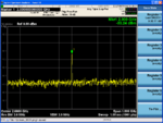
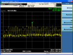
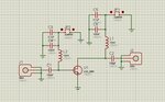
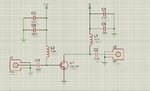
Hi, I have design an RF amplifier circuit for my assignment. As per attached are the measured result. The first results was a -30 dBm power is feed but the RF amp wasnt powered up. The second results shows a -30 dBm power is feed and RF amp was powered up. Obviously, I think my designed was wrong since I cant see any gain. But would like to know what is the definition for the harmonics effect when the RF amp was powered up? can anyone give your valuable suggestion and explanation? Thank you.
 

Attachments

  • 1.png
    1.png
    85.8 KB · Views: 109
  • 2.png
    2.png
    80 KB · Views: 106

Hi,

Well, harmonic effect appear when the input signal is too high that the amplifier response is non linear (over the 1 dB gain compression). Your signal seems to be very low. Perhaps, your design is wrong ? Have you well polarise your amplifier ? Does it work for the maximum gain ? Is it well matched ? Be carreful about oscillation ! Give us the shematic of your amplifier.

Bye
 

Most likely your amplifier is not properly biased and you just generate more harmonics from an internal junction of the transistor, similar as using a diode for harmonic generation.
 

Hi, as per attached is my design circuit which I used mini-circuit SAV-581+ amplifier. If I first ignore the matching part, but I dont understand the circuit doesnt give any amplification but the harmonics appeared everywhere.. This is really trouble me.. :(
 

Attachments

  • amp.jpg
    amp.jpg
    121.6 KB · Views: 110

So, I did assume correctly.
There is no DC bias on your amplifier stage.
No drain bias and no gate bias.
 

Hi vfone, thanks for the feed back. I thought the tune the bias input from the voltage supply where Vds = 0.4V and Vgs = 4 V? is this correct? The jumper is the voltage supply input.
 

Hi vfone, thanks for the feed back. I thought the tune the bias input from the voltage supply where Vds = 0.4V and Vgs = 4 V? is this correct? The jumper is the voltage supply input.
They should be inverted so Vds=4V, Vgs=0.4V.( I don't know the specification of your FET that you used, I'm not sure it will conduct at Vgs=0.4V)
 

It should be fine with Vgs = 0.4 V, according to https://www.minicircuits.com/pdfs/SAV-581+.pdf . Should give a gain of just under 17.5 dB, if I read the plots correctly.

@YY, are pins 2 and 4 of the mini-circuit SAV-581+ connected to ground? And you used the pin on the other side of the package from the wide pin, and directly across from it, as the input (gate)? And you used the pin on the same side of the package as the wide pin as the drain?
 

Hi tgootee,

Thanks a lot for the comment. yes, I shorted pin2 and pin4 to ground. I use pin3 as the input (gate) and pin1 (drain) as my output. the circuitry is just as shown as the schematic that I shown previously. Correct me if there is something wrong..
 

...the harmonics appeared everywhere..
That's not harmonics, it's intermodulation distortion. The amplifier is oscillating at a much lower frequency.

What is the spacing between the spikes in the spectrum? It looks like they are about 30MHz apart, if I understand the scale correctly.

If so, then amplifier is oscillating at 30MHz, and producing strong output at 30MHz, 60MHz, 90MHz, 120MHz etc. What you see in the output spectrum is the intermodulation products of those frequencies and the 2GHz input.
 
Hi godfreyl, yes, the harmonics is around 30MHz. But I have no idea why does the amp oscillating. I have tried to search around but not clues yet. Mind to share with me how can I solve this? Besides, I not sure why the amplifier doesnt amplified my desired frequency but the harmonics was everywhere when I powered up the circuit. :(
 

Did you fix the DC, per post number 7?

It appeared that you had the "jumpers" swapped, i.e. with the DC bias voltages at the wrong locations.

Can you please post a proper schematic, showing actual DC bias voltages and their polarities, instead of jumpers. Jumpers are not correct, and were misleading initially. And now there is still confusion about what DC voltages are being applied, at each location.
 
Last edited:

Hi tgootee,

Thanks for the feedback. Sorry where I named it wrongly previously. I powered up my circuit with Vgs = 0.4V and Vds = 4V actually. Sorry for the confusion, I have updated the schematic (as per attached). Would like to have your further advise and suggestion. Thank you very much.
 

Attachments

  • amp1.jpg
    amp1.jpg
    267.4 KB · Views: 87

Hi,
Firstly, it seems to me that your inductor of 10 nH is to low for biasing the fet. Increase it. If the desired frequency is 2 GHz so jLw = 10e(-9) * 2 * PI * 2e(9)=125 Ohms
So there is perhaps a leakage of your 2 GHz signal and only a part of it is amplified. Secondly, there are no biased resistor see the datasheet of your transistor ...
Thirdly, for stability compute the K parameter to verify if your transistor is unconditionally stable.

Bye for now...
 
Last edited:

place the probes at exactly the gate and drain after the biasing circuit and see what are you getting ......
secondly play around with inductor values and see what difference is it making .....
finally if it is oscillation the simplest solution that might work will be to place a 2 ohm resistor in the base of the transistor.....
 
i agree with tgootee about "http://www.minicircuits.com/pdfs/SAV-581+.pdf ". It has S-parameter to define DC bias, then you do.
i should use ADS to simulate your circuit.
 

Hi All, thanks for all the valuable advice. I have tried to changed the inductance value to 100nH but there is still no amplification at the 2GHz. However, I found that there is a amplification at lower frequency, 6 dB gain @ 600 MHz. Would like to know is there anyone can explain this phenomena to me? And is there any other way i can improve the amplifier performance at 2GHz?
 

Maybe you can post a pic of your measurement setup, or do you have also no gain in sim?
 

Hi tgootee,

Thanks for the feedback. Sorry where I named it wrongly previously. I powered up my circuit with Vgs = 0.4V and Vds = 4V actually. Sorry for the confusion, I have updated the schematic (as per attached). Would like to have your further advise and suggestion. Thank you very much.

GND connections are extremely important for a reliable stability of monolithic RF amplifiers.On the PCB, you should use many vias just underneath of the GND pad of the package as mentioned as in app.notes or datasheet.If you don't connect GND pad(s) of the amplifier well, amplifier will see some inductance at the emitter/source and then it will act as a oscillator because of series positive feedback.
 
Hi,

Thanks a lot for all the feed back and suggestion. I had successfully solved the problem by adding the ground vias. At least i got a 16dB gain at 2GHz now. Would need to solve the biasing problem so that I can push up to higher frequency. Thanks..!
 

Status
Not open for further replies.

Part and Inventory Search

Welcome to EDABoard.com

Sponsor

Back
Top