Continue to Site

Welcome to EDAboard.com

Welcome to our site! EDAboard.com is an international Electronics Discussion Forum focused on EDA software, circuits, schematics, books, theory, papers, asic, pld, 8051, DSP, Network, RF, Analog Design, PCB, Service Manuals... and a whole lot more! To participate you need to register. Registration is free. Click here to register now.

How do you calculate Fifo depth for Asynchronous clock having same frequency ?

Status
Not open for further replies.

coolasic

Newbie level 5
Joined
Feb 27, 2013
Messages
8
Helped
2
Reputation
4
Reaction score
2
Trophy points
1,283
Activity points
1,345
Hi,

Frequency of 2 clock domains are same but they are asynchronous . How do you transfer the data from one domain to other domain ? If we use FIFO what should be the depth of the FIFO ? Since both are the same clock frequency and phase relation we cant determine since it is asynchrous and the Input data is continous.

Thanks
 

To avoid metastability, double flip-flops is enough.
If you know the phase margin you have you could ignore the metastability effect.
 

From what i know , If you add the double flip flops on the data, we might not register the correct data in the other domain . Reason being its not timing closed , since the clock is asynchronous. So adding the synchronizers is not advisable . And i dont know the phase margin also . Its pure asynchronous clock .
 

Hi coolasic,

you are right, you will need a simple asynchrnous fifo.

You have continous write and read data.
So your write and read pointer increases with every clock cycle. So you "just" have to make sure that the two pointers start after reset with the correct offset.
You can do like this.
After reset both pointer are at zero. When write pointer goes to 1 you set a flag. This flag is synchronized to the read side with 2 flipflops (running with the read clock) and starts the read pointer.
With this the offset will be between 2 and 3. I think 4 FIFO entries are enough. To be on the save side you can use 5 FIFO entries.

What do you think.

regards
 
In order to avoid data lost, it is desirable insert some little randomic delay at transmiter.
It could be enough to certify no occurence of traffic jam.
Then, few flip-flops could succeed.


+++
 

Hi qieda,

The Fifo depth is correct. But i think it might not work.
Since its asynchronous domain and we dont know the clock phase difference.
From your solution , Initially the 1st data is valid for few cycles and then the data will start poping out for every clock cycle. The data will be changing every clock between the 2 clock domain. So now it totally depends on the phase difference between the clock. The data might or might not get flopped in the other domain , isn't it ?
I think simple fifo wont suffice , there should be some other solution for it.

Thanks.
 

...I think simple fifo wont suffice , there should be some other solution for it...

It is not true if the data traffic is designed so that transmiter rate is lower than receiver prompt capacity to process it. As suggested previously, a simple delay coluld be enought to fit and no stochastic model stream would be required to predict fifo amont than fews FF.


+++
 

Yes you are right if the TX rate is lower than the RX rate .
But if both TX and RX rate are same and if the clock are asynchronous (no control over the phase) then the simple fifo wouldnt work . RX rate should be @least 1.5 times more than the TX clock if it needs to work in asynchronous domain, if the phase is not controllable . Isn't it ?
 

Hi coolasic,

I think we have a different understanding of the structure of the fifo. I attached a picture.
The write side writes into entry 0,1,2,3,4,0,1,2,3,4,...
The read side reads at the same time from 3,4,0,1,2,3,4,0,1,....
If the clock phase is shifted the readout may be one entry earlier or later.
But still no conflict.


regards
 

...if both TX and RX rate are same and if the clock are asynchronous...

Ok...but despite TX/RX baud rate are the same, the overall transmission / reception rate capability could be different.
If some delay is inserted at transmiter, it could be enought to receiver acquire and process whole data.


+++
 

coolasic wrote

Input data is continous

so I assumed the question is about clock domain crossing of a continous data stream.

regards
 

Yes it is Clock Domain Crossing .
Since both the clocks are the same frequency , how are we avoding the read flop from going to metastability ? Let say the clock skew is such that the read flop setup time is violated . How can we guarantee that the read flop wont go to metastability ? Point to be noted we dont have control over the clock phase .
 

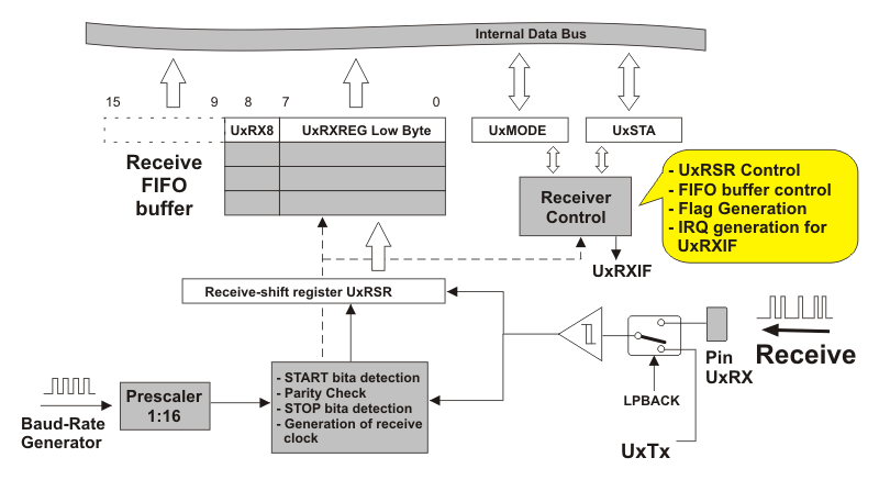
Some Microcontrolers UARTs modules already have built-in data FIFO.
For instance, at PIC16F fammilies, their deep is 3 bytes, and at LM CORTEX-M3 fammily is 16 bytes :

M3
127FCC0F4B283C9F271CA5

PIC
fig10-5.gif


+++
 
Last edited:
How can we guarantee that the read flop wont go to metastability ?

The flop on the read side will only be metastable if the D input of the flop changes during the clock rise time (in the setup/hold window).
But in the design the multiplexer always selects a write flop which has a stable output when the read flop latches the data.
The written data on the write side goes always to a different flop
So you will never be metastable.

regards
 
Since you have a MUX logic between the one clock to the other clock domain , will it be optimized in synthesis . Reason am asking this is because , Async clocks will be treated as false paths. Will it be synthesized with some special care ?

Thanks
 

Hi,

yes you are right, the path with the mux will be a false path. So in theory it could be long. I think to be on the save side you need to make a constraint, which makes sure that the delays trough the mux is not longer than ~ 1clock cycle.

regards
 

Status
Not open for further replies.

Part and Inventory Search

Welcome to EDABoard.com

Sponsor

Back
Top