Continue to Site

Welcome to EDAboard.com

Welcome to our site! EDAboard.com is an international Electronics Discussion Forum focused on EDA software, circuits, schematics, books, theory, papers, asic, pld, 8051, DSP, Network, RF, Analog Design, PCB, Service Manuals... and a whole lot more! To participate you need to register. Registration is free. Click here to register now.

[SOLVED] PCB with Eagle and photoshop help

Status
Not open for further replies.

varunme

Advanced Member level 3
Joined
Aug 10, 2011
Messages
741
Helped
17
Reputation
36
Reaction score
17
Trophy points
1,318
Activity points
5,764
I exported 300dpi image from eagle and pasted into a A4 300dpi blank image, but when i took the print out , the sizes of the ICs are not matching, what can be the problem ?
 

There could be a few problems. Did you make sure that when you exported the image that you exported it at a scale of 1:1? That might help.

Also, from my experience, when printing/exporting the PCB layout as an image, Eagle always seems to be a little off with the size. What I would recommend doing is to mess with the zoom/scale until the printout matches the actual dimensions. Then your ICs should match up perfectly.

Regards,
Willis
 
  • Like
Reactions: varunme

    varunme

    Points: 2
    Helpful Answer Positive Rating
There could be a few problems. Did you make sure that when you exported the image that you exported it at a scale of 1:1? That might help.
1:1 , i didnt understand , how can i do it ?
 

1:1 , i didnt understand , how can i do it ?

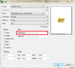
Are you just trying to print/export an image of the board layout, correct? If so, you need to ensure that you are trying to print at a 1:1 scale. To do this make sure that box that says "Scale Factor" has a 1 in it; otherwise your layout image will be either bigger or smaller than it should be.

eagle print.PNG

Regards,
Willis
 
  • Like
Reactions: varunme

    varunme

    Points: 2
    Helpful Answer Positive Rating
ok ,
but i exported the image as bitmap from Eagle.
I will try the print method with the scale factor as 1.
 

@varunme, I agree with willis here. Using the scale of 1:1 is a must in order to print the correct layout image.:razz:
 

You may want to look at how you are "printing it" from the image. I exported an image of a PCB from Eagle at 300dpi and examined the resulting png file in a photo editor and the number of pixels is exactly correct.

Keith
 
  • Like
Reactions: varunme

    varunme

    Points: 2
    Helpful Answer Positive Rating
creating bit map artworks is not a recomended way of doing things, again I go with printing 1:1 or if eagle has a bespoke post processing option for creating artworks use that.
 
  • Like
Reactions: varunme

    varunme

    Points: 2
    Helpful Answer Positive Rating
I exported to pdf using nitropdf using scale of 1:1, and took print of pdf , now too the scale is not correct , IC legs dont match
 

As I said earlier, you need to look at how you are printing the image. Adobe pdf Reader usually selects "fit to page" by default - you need to turn that off.

You could post your pdf here.

Keith
 
  • Like
Reactions: varunme

    varunme

    Points: 2
    Helpful Answer Positive Rating
I am using nitropdf

I am posting a dummy file that is printed with eagle and nitropdf
 

Attachments

  • mybrd.zip
    3.7 MB · Views: 110

I have printed that 1:1 from Adobe and the pitch of IC1 is 2.526mm - is that what you are measuring? That is probably paper shrinkage in my laser printer. Measuring the pdf (by eye, at 1000 pixles per inch) it seems to be 0.09989" pitch - close enough to 0.1". So, I think your pdf is OK. Your problem is printing.

Keith
 
  • Like
Reactions: varunme

    varunme

    Points: 2
    Helpful Answer Positive Rating
I am using nitropdf

I am posting a dummy file that is printed with eagle and nitropdf

varun ,
that is not the way you create a pdf from eagle. how do you use the artwork with components marked on that? Is it a screen for top layer?

EAGLE has inbuilt pdf creation possibility. while print ting , perhaps you select the layer needed as we dont need many other layers. then leave the printer selection second button allows you to save a pdf direct.

suppose the file is 'mybrd". now name the file as "mybrd sold" for solder layer and 'mybrd top" for top layer- incase two layer board. direct the file to be saved in the same foolder that holds the brd and sch files. it gives a clean correctly dimentioned artwork, once you select the print ratio as 1:1. you can print that pdf using adobe.

the printer sizing should be set to 'none' even the centring etc can be cancelled. I do many boards.like that and i get perfect diomentioning. Ofcourse i use 600dpi mode with my HP Laserjet P1007.
 
Last edited:
  • Like
Reactions: varunme

    varunme

    Points: 2
    Helpful Answer Positive Rating
just to check the pitch of the board , i checked all the layers and printed togather , i will try individual layers

- - - Updated - - -

yes, it's 2.54mm pitch, 16f877a
 

yes , finally figured out was a problem with printing , thanks all
 

Status
Not open for further replies.

Part and Inventory Search

Welcome to EDABoard.com

Sponsor

Back
Top