Welcome to our site! EDAboard.com is an international Electronics Discussion Forum focused on EDA software, circuits, schematics, books, theory, papers, asic, pld, 8051, DSP, Network, RF, Analog Design, PCB, Service Manuals... and a whole lot more! To participate you need to register. Registration is free. Click here to register now.
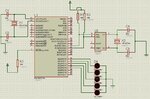
1. Vbat - should be connected to GND if is not used (if Vbat is not present, DS1307 will not keep calendar data when the board is unpowered)
2. SOUT - is an open collector output, it should have a pull-up resistor
3. DS1307 uses a 32.768 kHz crystal and not requires external capacitors
In the simulation, the VBAT pin wouldn't affect the simulation. But in real hardware, you need to connect a 3V battery from VBAT to ground (for battery backup) or connect VBAT to ground to have the DS1307 working without battery backup.
The SOUT pin is not used, so the pull-up resistor isn't needed.
As pointed out by cristianp, C3 and C4 are not required.
For the LEDs, you need to use current-limiting resistors. Connect resistors between the PORTD pins and the LED anodes to limit the current. You have to choose resistors to allow a maximum current of 20mA (provided these are standard LEDs). 10mA is enough current.
This site uses cookies to help personalise content, tailor your experience and to keep you logged in if you register.
By continuing to use this site, you are consenting to our use of cookies.