Continue to Site

Welcome to EDAboard.com

Welcome to our site! EDAboard.com is an international Electronics Discussion Forum focused on EDA software, circuits, schematics, books, theory, papers, asic, pld, 8051, DSP, Network, RF, Analog Design, PCB, Service Manuals... and a whole lot more! To participate you need to register. Registration is free. Click here to register now.

[SOLVED] How to find the radius of curvature MCURVE value for the 180 degree HYBRID COUPLER?

Status
Not open for further replies.

btv_murthy

Full Member level 3
Joined
Nov 29, 2011
Messages
159
Helped
9
Reputation
18
Reaction score
9
Trophy points
1,298
Location
BANGALORE
Activity points
2,719
Dear sir,
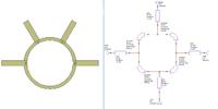
I don't know,how to find the value of RADIUS OF CURVATURE value of MCURVE of Hybrid coupler. Presently I am getting the S-PARAMETER values for the 180 deg HYBRID COUPLER as follows for both schematic and EM simulation.

for schmatic simulation S(1,1), S(2,1), S(3,1), S(4,1) for EM SIMULATION S(1,1), S(2,1), S(3,1), S(4,1)

-6.3478DB, -5.2062DB, -10.707DB, -6.7046DB 6.3478DB, -5.2062DB, -6.7046DB, -10.707DB
I am expecting the following values.

for schmatic simulation S(1,1), S(2,1), S(3,1), S(4,1) for EM SIMULATION S(1,1), S(2,1), S(3,1), S(4,1)

-34 DB, -3.001DB, -3.001DB , -34DB -34 DB, -3.001DB, -3.001DB , -34DB

I am here wtih attaching the schematic ,layout and related document. Please help me any body to resolve this problem.
 

Attachments

  • Hybrid coupler.jpg
    Hybrid coupler.jpg
    69.1 KB · Views: 257
  • Hybrid coupler layout.jpg
    Hybrid coupler layout.jpg
    28.9 KB · Views: 268
  • 10-180 HYBRID COUPLER.doc
    198 KB · Views: 178

Hi,

You layout is wrong. It's not even close to what it should look like. I think you should draw the Rat-race coupler on an EM simulator instead. The Rat-race coupler has a ring shape. One way of drawing the structure would be subtracting one circle from another. The difference between the two radius should be the width that translate to 1.4 Zo.

Hope this helps,

Microwave123
 

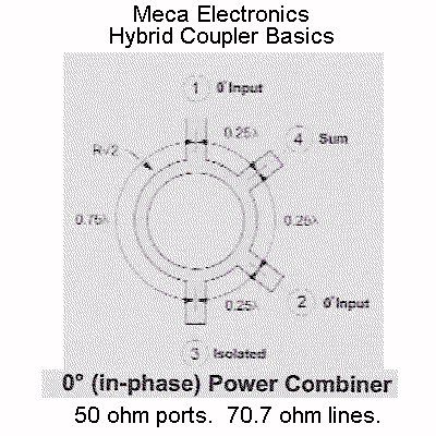
normally the angle is 90 deg, and you should combine several mcurves to get the needed shape.
 

RatRaceCombiner.jpg


The circumference of the ring should be 6/4*lambda. One half will be 3 quarterwave sections, the other half will be a single 3/4-wavelength section. Use a transmission line calculator to find the length of a quarterwave line; that will be the arc-length for one section, which will take up 360/6 = 60 degrees. The 3/4-wavelength side will sweep out 180 degrees.

A little bit of math should get you any other values that you are looking for. Recall C = 2*pi*radius, and arc length = C*angle/360.
 

enjunear sir,

If three sides angle is equal to 60 degees, what will be radius of curvature. If one side is equal to 180 degrees, what will be the radius of curvature.

---------- Post added at 12:12 ---------- Previous post was at 12:11 ----------

enjunear sir,

If three sides angle is equal to 60 degees, what will be radius of curvature. If one side is equal to 180 degrees, what will be the radius of curvature.

---------- Post added at 13:14 ---------- Previous post was at 12:12 ----------

:?::| how to find the radius of curvature for the three 60 degrees angles and one 180 degree angle t

As I stated before, the three 60 degree sections need to be one-quarter of a wavelength long at your frequency of interest (center frequency). Use a microstrip calculator (or equations from a microwave circuit design textbook) to find the length of a quarterwave line.
 
enjunear Sir,

How to find the radius of curvature of any side. Mine 180 degree hybrid coupler ,what will be the radius of curvature for three 60 degree sides and one 180 degree sir, Please help me sir.
 

As I stated before, the three 60 degree sections need to be one-quarter of a wavelength long at your frequency of interest (center frequency). Use a microstrip calculator (or equations from a microwave circuit design textbook) to find the length of a quarterwave line.

enjunear sir,
Here I am attaching two files, those examles given in the AWR software. How they found out the radius of curvature value , I don't know sir, what is the resonator length , how we have to take , he didn't tell anything . Please if you understood , please tell me sir.
 

Attachments

  • Wilkinson curved power divider.png
    Wilkinson curved power divider.png
    54.7 KB · Views: 202
  • Wilkinson curved layout.png
    Wilkinson curved layout.png
    23.9 KB · Views: 184

enjunear sir,
How to find the radius of curvature for the MCURVE bend, One of the formula I read in IEEE paper. In that formula , what is 'We' and 'W', I couldn't get it. Please tell me ,what ie "We " and "W" . If any other formula to calculate the radius of curvature .Please help me descriptively. IEEE formula as follows


R_e=R/2 + 1/2 √(R^2+(W_e-w)w_e )
 

If you are trying to make a ring hybrid (a.k.a. Rat Race), this should not be this difficult (i.e. your thinking too hard). To construct the ring, take 4 MCURVEs, set them to have the same radius (just pick a number at random, to get started). Make three of them angle=60 deg, and one of them angle=180 deg. Connect them end-to-end, so they make a complete circle. At each of the connection points, add an MLIN that is rotated such that it's perpendicular to the arc (so it sticks out, and points away from the center of the ring).

Once you have the circle and input/output lines, change the radii of the ring sections to all be the same value, so the circle remains a nice, connected circle. Then, using LineCalc, determine the length of each 60 degree MCURVE such that it's arc length equals 1/4th of a wavelength (for linecalc: electrical length = 90 degrees). Also, make thering section widths such that they have a characteristic impedance of 1.414*Z0. If Z0 = 50 ohms, then the circle must have lines that are ~70.7 ohms. All of the radial input & output lines will have a width congruent with Z0 = 50 ohms.

Enjunear Sir,
I tried as you said in the previous replay,and followed each and every step as said sir. I am getting little extension in the one of the curvature. I couldn't find out , where I am doing mistake and I designed the rat race coupler for the following values
f= 3GHz, Z0= 50 Ohms, H=1.6mm, T=0.036mm, relative permitivity =4.4.
I have calculated and substituted the "R" value as you mentioned formula,the formula and obtained value as follows
ArcLength =2 PI R C/360 , where C is the central angle of the arc in degree
R is the radius of the arc.

ArcLength = 2*3.14 R 60/360
14.0083 =2*3.14 R 1/6
R = 13.3837261.
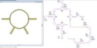
The above 'R' value substituted as 'R' value in MCURVE, I am getting the little extension one leg ,and could find it mistake. Here with I am attaching the schematic, layout and related document for the RAT RACE COUPLER . Please see sir and give me descriptively , where I am doing the mistake, what value need to substitute to get the desired ring shape. Please help me sir.
 

Attachments

  • RAT RACE COUPLER.jpg
    RAT RACE COUPLER.jpg
    61.1 KB · Views: 269
  • RAT RACE LAYOUT.png
    RAT RACE LAYOUT.png
    20.8 KB · Views: 228
  • 10-180 HYBRID COUPLER.doc
    198 KB · Views: 116

Enjunear Sir,
I tried as you said in the previous replay,and followed each and every step as said sir. I am getting little extension in the one of the curvature. I couldn't find out , where I am doing mistake and I designed the rat race coupler for the following values
f= 3GHz, Z0= 50 Ohms, H=1.6mm, T=0.036mm, relative permitivity =4.4.
I have calculated and substituted the "R" value as you mentioned formula,the formula and obtained value as follows
ArcLength =2 PI R C/360 , where C is the central angle of the arc in degree
R is the radius of the arc.

ArcLength = 2*3.14 R 60/360
14.0083 =2*3.14 R 1/6
R = 13.3837261.
The above 'R' value substituted as 'R' value in MCURVE, I am getting the little extension one leg ,and could find it mistake. Here with I am attaching the schematic, layout and related document for the RAT RACE COUPLER . Please see sir and give me descriptively , where I am doing the mistake, what value need to substitute to get the desired ring shape. Please help me sir.
 

Attachments

  • RAT RACE COUPLER.jpg
    RAT RACE COUPLER.jpg
    61.1 KB · Views: 187
  • RAT RACE LAYOUT.png
    RAT RACE LAYOUT.png
    20.8 KB · Views: 191
  • 10-180 HYBRID COUPLER.doc
    198 KB · Views: 121

Enjunear Sir,
I tried as you said in the previous replay,and followed each and every step as said sir. I am getting little extension in the one of the curvature. I couldn't find out , where I am doing mistake and I designed the rat race coupler for the following values
f= 3GHz, Z0= 50 Ohms, H=1.6mm, T=0.036mm, relative permitivity =4.4.
I have calculated and substituted the "R" value as you mentioned formula,the formula and obtained value as follows
ArcLength =2 PI R C/360 , where C is the central angle of the arc in degree
R is the radius of the arc.

ArcLength = 2*3.14 R 60/360
14.0083 =2*3.14 R 1/6
R = 13.3837261.
The above 'R' value substituted as 'R' value in MCURVE, I am getting the little extension one leg ,and could find it mistake. Here with I am attaching the schematic, layout and related document for the RAT RACE COUPLER . Please see sir and give me descriptively , where I am doing the mistake, what value need to substitute to get the desired ring shape. Please help me sir.

This should be obvious, why you're not lining up... you're adding length by sticking TEE's in between the arcs. If you remove the TEEs, then the circle should be perfect, right? (I forgot that you're using MWO, not ADS, which would allow you to snap two arcs and an MLIN together at one common point.)

What you'll have to do to make that layout work is reduce the length of your arcs by 1x the width of your TEEs, and decrease the swept angle of each accordingly (which will vary as a function of radius). Since you will no longer snapping end to end perfectly, you may need to modify your layout by adding a "wedge" to get the faces to meet up correctly (you may see one of the faces not snap together due to the offset caused by the straight sections of the TEEs).
 
Enjunear Sir,
Sir please help me sir, I am once again posting previous post to you once again sir. Please help me sir.
I tried as you said in the previous replay,and followed each and every step as said sir. I am getting little extension in the one of the curvature. I couldn't find out , where I am doing mistake and I designed the rat race coupler for the following values
f= 3GHz, Z0= 50 Ohms, H=1.6mm, T=0.036mm, relative permitivity =4.4.
I have calculated and substituted the "R" value as you mentioned formula,the formula and obtained value as follows
ArcLength =2 PI R C/360 , where C is the central angle of the arc in degree
R is the radius of the arc.

ArcLength = 2*3.14 R 60/360
14.0083 =2*3.14 R 1/6
R = 13.3837261.
The above 'R' value substituted as 'R' value in MCURVE, I am getting the little extension one leg ,and could find it mistake. Here with I am attaching the schematic, layout and related document for the RAT RACE COUPLER . Please see sir and give me descriptively , where I am doing the mistake, what value need to substitute to get the desired ring shape. Please help me sir.
 

Attachments

  • RAT RACE COUPLER.jpg
    RAT RACE COUPLER.jpg
    61.1 KB · Views: 187
  • RAT RACE LAYOUT.png
    RAT RACE LAYOUT.png
    20.8 KB · Views: 205
  • 10-180 HYBRID COUPLER.doc
    198 KB · Views: 116

Enjunear Sir,
I tried as you said in the previous replay,and followed each and every step as said sir. I am getting little extension in the one of the curvature. I couldn't find out , where I am doing mistake and I designed the rat race coupler for the following values
f= 3GHz, Z0= 50 Ohms, H=1.6mm, T=0.036mm, relative permitivity =4.4.
I have calculated and substituted the "R" value as you mentioned formula,the formula and obtained value as follows
ArcLength =2 PI R C/360 , where C is the central angle of the arc in degree
R is the radius of the arc.

ArcLength = 2*3.14 R 60/360
14.0083 =2*3.14 R 1/6
R = 13.3837261.
The above 'R' value substituted as 'R' value in MCURVE, I am getting the little extension one leg ,and could find it mistake. Here with I am attaching the schematic, layout and related document for the RAT RACE COUPLER . Please see sir and give me descriptively , where I am doing the mistake, what value need to substitute to get the desired ring shape. Please help me sir.
 

Attachments

  • RAT RACE COUPLER.jpg
    RAT RACE COUPLER.jpg
    61.1 KB · Views: 182
  • RAT RACE LAYOUT.png
    RAT RACE LAYOUT.png
    20.8 KB · Views: 213
  • 10-180 HYBRID COUPLER.doc
    198 KB · Views: 118

Enjunear Sir,
I tried as you said in the previous replay,and followed each and every step as said sir. I am getting little extension in the one of the curvature. I couldn't find out , where I am doing mistake and I designed the rat race coupler for the following values
f= 3GHz, Z0= 50 Ohms, H=1.6mm, T=0.036mm, relative permitivity =4.4.
I have calculated and substituted the "R" value as you mentioned formula,the formula and obtained value as follows
ArcLength =2 PI R C/360 , where C is the central angle of the arc in degree
R is the radius of the arc.

ArcLength = 2*3.14 R 60/360
14.0083 =2*3.14 R 1/6
R = 13.3837261.
The above 'R' value substituted as 'R' value in MCURVE, I am getting the little extension one leg ,and could find it mistake. Here with I am attaching the schematic, layout and related document for the RAT RACE COUPLER . Please see sir and give me descriptively , where I am doing the mistake, what value need to substitute to get the desired ring shape. Please help me sir.

Enjunear already answered your question. the problem is the TEE which you placed between the MCURVE's.
Another alternative is to draw your ratrace on an EM Planar simulator.

Since you already have the dimensions required from your calculations. Just make two circles, one with a radius equal to [R+(microstrip width)/2], the other with [R-(microstrip width)/2], subtract the smaller from the bigger, then make 4 microstrip lines, and attach them at 0deg, 60deg, 120deg, and 180 deg wrt to an arbitrary point on your circle. then just put the ports and simulate.
 

How to find the radius of curvature MCURVE value for the 180 degree HYBRID COUPLE

Enjunear already answered your question. the problem is the TEE which you placed between the MCURVE's.
Another alternative is to draw your ratrace on an EM Planar simulator.

Since you already have the dimensions required from your calculations. Just make two circles, one with a radius equal to [R+(microstrip width)/2], the other with [R-(microstrip width)/2], subtract the smaller from the bigger, then make 4 microstrip lines, and attach them at 0deg, 60deg, 120deg, and 180 deg wrt to an arbitrary point on your circle. then just put the ports and simulate.

Dear sir,
Earlier you told to make 2 circles, later told to add 4 microstrip lines. Please explain me in detail how to do that. Explain descriptively, Otherwise do whatever changes to my attachments and send the corrected my attachments sir.
 

This should be obvious, why you're not lining up... you're adding length by sticking TEE's in between the arcs. If you remove the TEEs, then the circle should be perfect, right?

That works indeed. The problem is that the electrical model for the T-junction is missing now. Nice layout if we set the correct direction for the feedlines, but electrical results are not quite correct.


The better alternative is to include the T-junctions. One "simple & stupid" method would be to also use 3 * 60° segments, and insert line segments with L=w50 which is the equivalent length of the T-junction. Finally, reduce the radius by all that extra length, so that we have R'=R - (6*w50)/(2*pi)


Attachments

  • ratrace.zip
    14.5 KB · Views: 114

That works indeed. The problem is that the electrical model for the T-junction is missing now. Nice layout if we set the correct direction for the feedlines, but electrical results are not quite correct.


The better alternative is to include the T-junctions. One "simple & stupid" method would be to also use 3 * 60° segments, and insert line segments with L=w50 which is the equivalent length of the T-junction. Finally, reduce the radius by all that extra length, so that we have R'=R - (6*w50)/(2*pi)


Much agreed. The first version should give you the best performance in an EM simulator environment (AXIEM), which is the most representative of the real-world.

The second design will give you "correct" results in a simple component-based electrical model (solves fast). That type of analysis does not account for coupling effects between conductor elements, which can severely impact your design performance when you fabricate it. Maybe not on this particular device (looks pretty "circular", but other microstrip components may not be so forgiving).
 
Status
Not open for further replies.

Part and Inventory Search

Welcome to EDABoard.com

Sponsor

Back
Top