Continue to Site

Welcome to EDAboard.com

Welcome to our site! EDAboard.com is an international Electronics Discussion Forum focused on EDA software, circuits, schematics, books, theory, papers, asic, pld, 8051, DSP, Network, RF, Analog Design, PCB, Service Manuals... and a whole lot more! To participate you need to register. Registration is free. Click here to register now.

how to design new coupler block to AWR?

EDA_Chandler

Newbie level 5
Joined
Jan 2, 2024
Messages
9
Helped
0
Reputation
0
Reaction score
0
Trophy points
1
Activity points
66
Hi, everyone, I want to establish a RF network by VSS AWR, the RF network is like blass or nolen network which consists of many couplers, and the 4 port of coupler can be as a input port or output port. But the ports of the coupler from AWR system blocks are fixed definition, such as port1 and port2 can be input port or output port, but port3 and port4 have to be output port which is not what i want. Therefore, is there a way to design a new coupler which can meet my requirement or new library to add to AWR? THANKS very much!
 
"Couplers" have always 4 or more ports. If you don't want to use Coupled and Isolated ports, simply terminate them with 50 Ohm.
 
"Couplers" have always 4 or more ports. If you don't want to use Coupled and Isolated ports, simply terminate them with 50 Ohm.
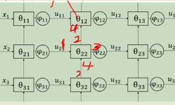
Thanks for your reply! I want to use the whole ports of a coupler including coupled and isolated ports, as shown in figure. And All the ports of a coupler can be input port and output port. However, the coupler block from AWR has predefined input ports and output ports, for instance, coupled port is defined as a output port not a input port. When the coupled port is used as a input port, there will be a error. So i wanna find another way to achieve below network. looking forward to your reply, thanks.

1.PNG
 
What are the expected properties of 4-port "coupler"? I expect it can be modeled as s-parameter matrix. What's the meaning of signal flow arrows in your schematic, port connections are basically bi-directional, even if the connected devices are non-reciprocal (e.g. active devices, circulators).
 
What are the expected properties of 4-port "coupler"? I expect it can be modeled as s-parameter matrix. What's the meaning of signal flow arrows in your schematic, port connections are basically bi-directional, even if the connected devices are non-reciprocal (e.g. active devices, circulators).
thanks for your reply!A symmetrical 4-port coupler is needed, Such as when port 1 is input port, port 2 is output port, port3 and 4 are coupled port and isolated port, respectively. Futhermore, port2, port3, or port 4 can also be a input port.
 
There is an element that you're potentially looking for.
View attachment 187479
Thanks for your reply! this element is the one that port 3 and port 4 are always output ports., which means that both of them can not be connected with the output port of another element. Only input port can connect with output port. However, in the network mentioned before, the 4 ports of coupler need to be as input port and output port.
1704273601833.png
 
Thanks to the response
Can you uploaded the model you used, I wanted to see how you solved it?

Thanks for your reply! this element is the one that port 3 and port 4 are always output ports., which means that both of them can not be connected with the output port of another element. Only input port can connect with output port. However, in the network mentioned before, the 4 ports of coupler need to be as input port and output port.
View attachment 187481
Mr. EDA_Chandler,

This Directional Coupler is a reciprocal element so you can use ANY Port as Input or Output since the s-parameter transfer matrix is given.
There is no restriction on Passive AND Reciprocal Circuit elements. If you have paid attention, you will clearly see that the Matrix is absolutely Symmetric so this component is Reciprocal.
More info : Passivity and Reciprocity of Passive Devices in textbooks.
 
This Directional Coupler is a reciprocal element so you can use ANY Port as Input or Output since the s-parameter transfer matrix is given.
True regarding real world physics, but note the limitation in the very last sentence of the screenshot in your post #8.
 
1. Define your detailed I/O Design Specs
2. Choose your topology
3. Design it according to above
4. Verify by simulation to meet spec
5. Build, Test, Verify
5. Repeat until meets spec.

View attachment 187496
REF


https://www.cadence.com/en_US/home/resources/datasheets/awr-visual-system-simulator-ds.html

Thanks for your input! yeah, we want to use AWR VSS to design the nolen matrix, the coupler is chosen as below figure. and error has been generated.

View attachment 187503
1704335730847.png

1704335741882.png
 
Mr. EDA_Chandler,

This Directional Coupler is a reciprocal element so you can use ANY Port as Input or Output since the s-parameter transfer matrix is given.
There is no restriction on Passive AND Reciprocal Circuit elements. If you have paid attention, you will clearly see that the Matrix is absolutely Symmetric so this component is Reciprocal.
More info : Passivity and Reciprocity of Passive Devices in textbooks.
True regarding real world physics, but note the limitation in the very last sentence of the screenshot in your post #8.
Thanks for your reply! we have used AWR VSS to realize the nolen network as follows, then a error has been generated.
1704336263975.png

1704336243780.png
 
yah it's hooked up wrong. msg is correct View attachment 187510


Do you see any outputs connected to each other below?
View attachment 187511
thanks for your reply! yeah, it will be generated between below coupler and above coupler as below, such as the connection between port 2 and port 4. Becasue the coupler we used has the definition that when port 1 is input port, port2, 3, 4 will be output port. So the connection between port2 and port 4 will be outputs connected each other.
1704340536401.png
1704340833509.png
 
Connect a small series resistance ( 0.01 Ohm). That's the trick..
Thanks for your suggestion! I have tried this method. but the same error were generated. I guess that the other port of the small series resistance will be defined as output ports when one port of resistance is connected with outputs. So the situlation of the connection between outputs is still existed.
 

LaTeX Commands Quick-Menu:

Part and Inventory Search

Welcome to EDABoard.com

Sponsor

Back
Top