Introduction:
One of the most overlooked, least thought-out components assembled to a PCB is the pin terminal. Although they’re not exciting like logic devices, they can present complications to those who disregard their correct application.
Consider the profit loss of fully populated PCBs residing in a trash can if you discover the chosen pin connector does not fit into your plated through holes or correctly match your footprint pattern.
Or consider the loss of fully populated PCBs lost due to cold solder joints because you missed that the connector pin lengths are too short and
do not protrude beneath your PCB preventing solder wicking.
Reworking solder joints is not a viable option.
So, it is wise to understand more about this type of component.
Methods of Pin Retention
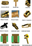
There are primarily three different pin retention methods to consider: thru-hole soldering, SMT reflow soldering, and mechanical fastening.
For soldering processes, male header pins are wave soldered for through-hole printed circuit boards or reflow soldered in pin-in-paste method and surface mount applications.
For situations requiring post-soldering assembly, pins can be designed for press-fit or mechanically fastening. A press-fit barb is good for lancing the pin into a soft, malleable material like soft plastic. A knurl is a press-fit retention feature preventing pin rotation when pressed into soft plastic. Solid polygon shapes like square and hexagonal features are sometimes pressed into plated through holes, but this form of pin retention can potentially damage the inner layer connections inside a PCB, or the retention can be compromised by the effects of temperature cycling.
Pin swaging is the riveting of a pin shoulder feature to the PCB.
Your comments and suggestions are welcome.
Please see the below chart.
Here is a PDF: https://drive.google.com/file/d/1tjWj7p6I1-OfVE8KtIW_PLv4V9IGCkIl/view?usp=sharing
