Continue to Site

Welcome to EDAboard.com

Welcome to our site! EDAboard.com is an international Electronics Discussion Forum focused on EDA software, circuits, schematics, books, theory, papers, asic, pld, 8051, DSP, Network, RF, Analog Design, PCB, Service Manuals... and a whole lot more! To participate you need to register. Registration is free. Click here to register now.

Zener Diodes in Parallel: WHY?

Status
Not open for further replies.

Chips & Chips

Junior Member level 3
Joined
Sep 21, 2012
Messages
31
Helped
7
Reputation
14
Reaction score
7
Trophy points
1,288
Activity points
1,707
An article for a constant Voltage power supply in the latest issue of Nuts & Volts magazine shows that the commercial module that the author uses has two 2.5V zeener diodes in parallel. They are in series with a 2.2K resistor which connects to the output of a 78L05 regulator chip. This arrangement supplies a reference Voltage (2.5V) to a couple of comparators for current limiting and charging complete functions.

I have never seen two zeener diodes connected in parallel and am completely puzzled as to why this was done. It does not increase the current as the 2.2K resistor will set that. It can not be for power dissipation as one zeener would only dissipate less than 3 mW. So why use two identical, zeener diodes in parallel?????

Nuts & Volts magazine, May 2014, page 28, figure 4.
 

Ask the author of the circuit. His e-mail is near the title of the article. Paralleling zener diodes is unusual to me too.
 
And I am puzzled by that also. Because of the voltage breakdown tolerance between zeners, one of the zeners will tend to hog most of the current, leaving the other one redundant.
 
Precision zener diodes are used and their type is not known. Because tight voltage tolerance diodes are in parallel it will cause small current difference (tolerable) between zener currents and some sort of averaging zener voltages may occur and precision can be better too. Just guessing.
 

Connecting Zeners in parellel just increases their capacity. Just in case of one watt resistors in parellel will have a capacity of 2 watts but with half the resistance of each resistors. Similarely the zener diodes when in parellel, will give double the power. If one diode is 1watt, its just like having 2.5volt 2 watt zener but the breakdown voltage here remains the same as both are of same value.
The author may have also choosen to use use a single diode with double the capacity but may not be available.
But in case a 2.5volt zener is parellely connected with 5.0volts zener, now the breakdown volatge is 2.5volts and the circuit will act as if the 5.0 is not connected and thus no value
 

Re: Ze(e)ner Diodes in Parallel: WHY?

May be it's for the same reason, why the OP writes the Zener diode with two "e" (serially, in this case): if one of them fails (goes OFF, ill-soldered, disconnected, or poorly printed), there's still one more to do the job.

SCNR ;-)
 

There must be a typo somewhere.
Your analysis that the power would be less than 3mW with the 2.2K is correct, and other than providing higher power capacity there is no logical reason.

Providing less than 3mW to a circuit is also unusual, because its so low. What IS this circuit ?

Could you post the article/ circuits ? Maybe there's something we are missing...
 

Here is the diagram in question.

From the description: "The LM358 compares the voltage drop across R3 to a set point established by variable resistor R6. R6 derives a precision reference voltage from zeners D2 and D3".

I think the idea is to get a sharper knee by using two zeners in parallel.

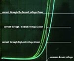
I have included a display from a curve tracer with 1-3 zeners (4.1 V) connected.
 

Attachments

  • sch_cvci.gif
    sch_cvci.gif
    117.1 KB · Views: 419
  • zeners.jpg
    zeners.jpg
    166.2 KB · Views: 367
Last edited:

I think the idea is to get a sharper knee by using two zeners in parallel.

I have included a display from a curve tracer with 1-3 zeners (4.1 V) connected.

I don't think the Zener knee becomes sharper by that: the lowest voltage Zener will win, the higher voltage Zeners just get less current:
3_zeners_in_parallel.jpg
 

Considering the supply is already a Regulated 5 Volts, Why use any Zeners?
Just a Resistor Divider should be OK.
 

The author does not provide a part number. Perhaps it is a dual device in a common package (like a sot23) and decided to use them both....because it is already there?

I'm Just guessing
 

I did some tests and measured the actual current through two zeners connected in parallel . These again were two randomly picked 4.1 V zeners of the same type from a tape reel. I was surprised how well they shared current between them. I was expecting one to channel more current, but that was not the case. The current was almost identical through both.

I could not find any part number for the zeners in the article. It is not in the parts list either.
 
Last edited:
Paralleling zener diodes means they have half of differential resistance and thus stabilisation factor is doubled.
 

Paralleling zener diodes means they have half of differential resistance and thus stabilisation factor is doubled.

Yes, if they have exactly the same breakdown characteristic.

And, is the differential resistance actually so important, if these Zeners are operated from a regulated voltage (s. chemelec's comment above) via a resistor, i.e. with constant current?
 

Yes both Zeners are matched and yes two parallel diodes will have lower ESR or dynamic differential resistance BUT ONLY IF THE SHARED current is well below the knee or well ABOVE the knee/

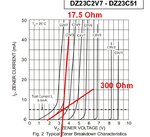
Two zeners in parallel will actually be worse than one Zener if he operated at the knee of 5mA as the shared current of 2.5mA increases the ESR by more than double negating the advantage of parallel.

Instead of using only 1.2mA and then using another diode with 270Ω for current limiting, had he changed the bias resistor from 2.2K to 470Ω for either the White LED or athe dual Zeners would out perform both Zeners for Load regulation or ESR. But then there is a 100mA limit on the L05 and power dissipation may also become a problem.

He would have been better off with lower ESR 7805 rather than an 78L05 and avoid the need for the zeners.


Rule of THumb. Use zeners or LEDs at >15% of rated current Minimum for good regulation. But still not as good as programmable Zeners using band-gap diode with Opamp.

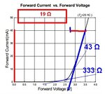
Now let's compare a typical White LED rated for 20mA ( some are better (15Ω) & some are worse)

LED Seoul.jpgDZ23.jpg

Because the designer chose to use an Integrator to regulate current limiting ANY drop in L05 Voltage from 220Ω diode load makes it wildly sensitive to mV variation in reference voltage. A drop in reference from L05 is due to its output ESR and the load from the current limiter diode going ON would be like an increase in Current sense voltage, THUS you have a positive feedback loop, causing it to have hysteresis and oscillate like a relaxation oscillator, THATS WHY he used two stages of regulation . It will still work but "motor-boat a bit" .. (read oscillate or porpoise)

IN CONCLUSION
It is important to understand Load regulation or current limit regulation is the ratio of source ESR to load variation of ESR ratio and if you want 2% load regulation make the source <2% of load variation. ( or 2% of full load if needed)

In this case two zeners at 300Ω ESR= 150Ω supplies voltage from 1.2K bias which improves supply regulation of L05 by 1200/150 =8x better due to load regulation problem on 78L05. The variation from Current limiting diode via 270Ω is the main issue. . Of course the OA could have been supplied by unregulated Voltage rather than load the 78L05.

Load regulation of 78L05 is in spec as follows;
ΔVO Load Regulation
1mA ≤ IO ≤ 100mA 20typ 60max [mV] means ESR = 0.2typ. 0.6max [Ω]
1mA ≤ IO ≤ 40mA 5typ 30max [mV] means ESR = 0.12typ. 0.75max [Ω]
and with 20mA switched diode current that translates into 0.02A x 0.75Ω =15 mV worst case ripple which evidently required better regulation using the zeners, again due to Integrator and positive feedback loop.

The 7805 has an output resistance of 8 mΩ typ which is 15x bettertyp.
 
Last edited:
A 2.5V zener diode is a lousy voltage regulator. Its dynamic resistance is high and its voltage drops when heated.
A zener diode with a breakdown voltage between 5.6V and 6.8V is MUCH better but a 2.5V reference IC is the best.
 

Status
Not open for further replies.

Part and Inventory Search

Welcome to EDABoard.com

Sponsor

Back
Top