Continue to Site

Welcome to EDAboard.com

Welcome to our site! EDAboard.com is an international Electronics Discussion Forum focused on EDA software, circuits, schematics, books, theory, papers, asic, pld, 8051, DSP, Network, RF, Analog Design, PCB, Service Manuals... and a whole lot more! To participate you need to register. Registration is free. Click here to register now.

Z matching, question about Q and loaded Q.

Status
Not open for further replies.

perlinpinpin

Newbie level 5
Joined
May 23, 2014
Messages
9
Helped
1
Reputation
2
Reaction score
1
Trophy points
3
Activity points
69
Hi,
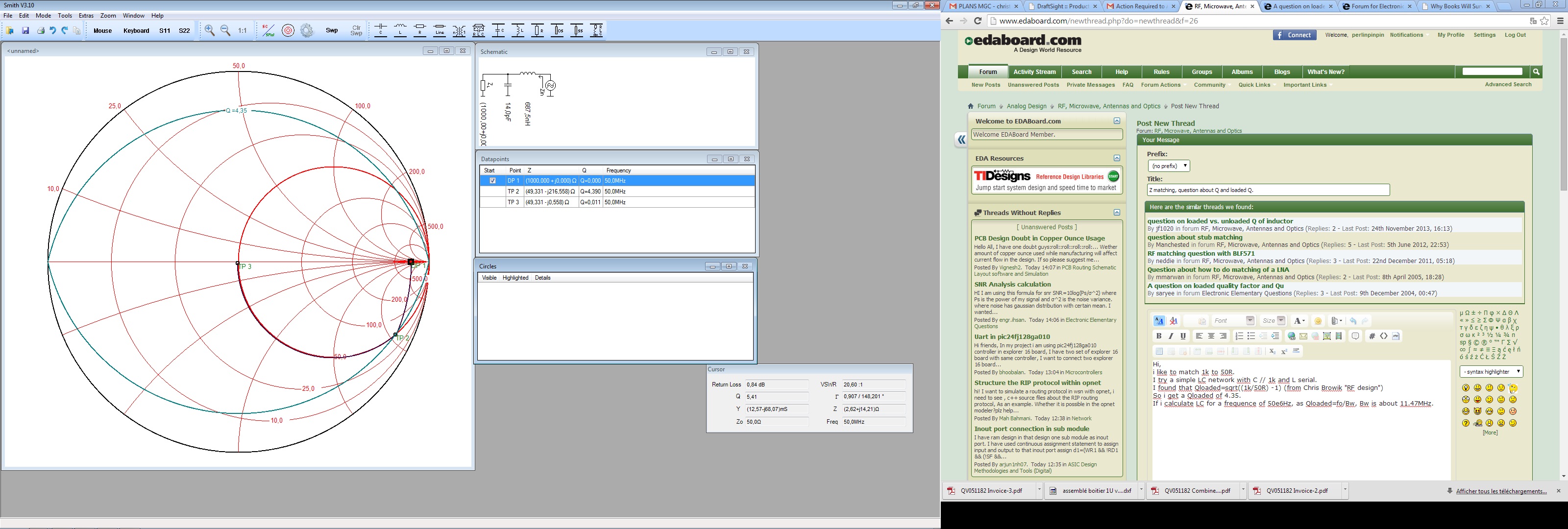
i like to match 1k(Rch) to 50R(Rs).
I try a simple LC network with C // 1k and L serial.
I found that Qloaded=sqrt((1k/50R) -1) (from Chris Browik "RF design")
So i get a Qloaded of 4.35.
If i use a smith chart and trace the matching procedure the max Q is 4.35
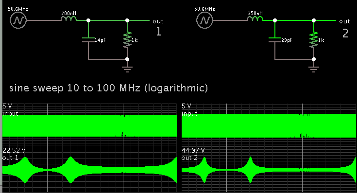
If i calculate LC for a frequence of 50e6Hz (L=687nH and C=14pF), as Qloaded=fo/Bw, Bw is about 11.47MHz.
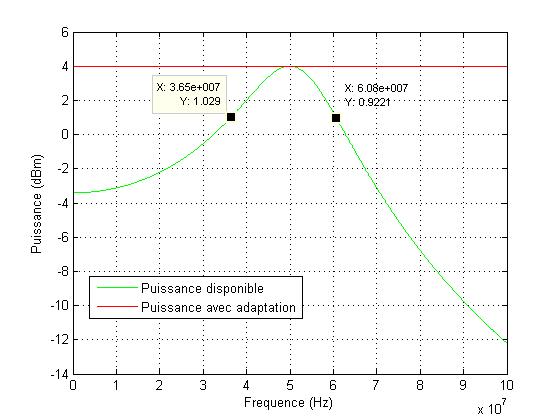
So now i'd like to perform a sweep from 10 to 100MHz and check the bandwidth of the matching.
I do a script on matlab to do the calculus and graph it.
Basicaly it gives (ZL stand for 1/j*C*2*pi*f and ZL...):
it= current of circuit= V/(Rs+ZL+(Rch//ZC)).
Current flowing into Rch equal it*(ZC/(ZC+Rch)) (current divider)
Power dissipating by Rch should be ((it*/(it))*Rch)/2. (/(it) stand for conjugate of course).
This is that last equation i plot.
I also plot the maximum available power V^2/8Rs (with a matched load 50R).
I'll add plot next time.
The problem is i get the adaptation at 50e6MHz but the bandwidth is wider i get an approximate 25MHz (-3dB bandwidth).
Someone has an idea?
Sincerely,


To make the bandwidth narrower, for this type of second-order filter (as displayed in your schematic)...

Reduce inductor value, and/or increase capacitor value.

This simulation shows (1) your schematic at left, and (2) a modified version at right.


If the LCR were all in series, then use the converse tactic (increase inductor, reduce capacitor).

I'm not sure how to account for the discrepancy in bandwidth which you observed in your results.
 

Hi Brad,
in your schematic there is no source resistance. With a source resistor you won't have choice about L and C value (with this topology).
My problem is why i get a smaller loaded Q than expected.
 
Last edited:

The "loaded Q" is the quality factor of the RLC circuit. The Q factor would be translated into a respective bandwidth fc/Q if you drive the circuit by a voltage or current source. For the bandwidth of the complete matching circuit, the 50 ohm source impedance must be considered, which about doubles the bandwidth.

You can increase matching circuit Q (within reasonable limits set by component losses and tolerances) by utilizing a second capacitor and implementing a CLC Pi-Filter.
 

The 50R (source resistor) is included in calculus: here is the script:
(note: "%" is the beginning of a comment)
Where i put ******* is to show a calculus of loaded Q from impedance. This caculus include every elements in network.

Rch=50; %impédance de référence /ref impedance
Rs=1000;
fo=50e6; %fréquence d'adaptation /frequency at which we perform matching
wo=2*pi*fo;

%calcul des éléments C en //Rs et L en série
% compute C and L from Rch Rs and fo
C=sqrt((Rs-Rch)/Rch)*(1/(Rs*2*pi*fo));%ok
L=((Rs^2)*C)/((1+(Rs*C*2*pi*fo)^2));
Z_C=1/(i*wo*C);
Y_C=Z_C^-1;
Z_L=i*wo*L;
Y_L=Z_L^-1;
Z_wo=((Y_C+Rs^-1)^-1 + (Z_L + Rch)^-1)^-1;
Q_wo=imag(Z_wo)/real(Z_wo);************
sprintf('Q_wo=%f',Q_wo)

%Puissance transmise VS fréquence
%Transmited power versus freuqency
V=1; %amplitude magnitude
f=fo/2:0.1e6:fo*2;
w=2*pi*f;
Zl=j*w*L;
Zc=1./(j*C*w);
%Zl=0;
%Zc=1e10;

it=(V/1.41)./(Rch+Zl+((Zc*Rs)./(Rs+Zc)));
Pp=(conj(it).*(it))*Rch;
Ptot=V/(8*Rch);
i1=it.*(Zc./(Zc+Rs));
Ps=(conj(i1).*(i1))*Rs;
%% ??
Va=(V*Rs)./(Rs+Rch+(j*w*(C*Rs*Rch+L))+((j*w).^2*(Rs*L*C)));
Pa=0.5*abs(Va).^2/Rs;


plot(f,10*log10(Ps/1e-3),'g');
hold on
plot(f,10*log10(Ptot/1e-3),'r');
grid on
xlabel('Frequency (Hz)');
ylabel('Puissancy (dBm)');
legend('Available Power','Adapted Power');
 

The "loaded Q" is the quality factor of the RLC circuit. The Q factor would be translated into a respective bandwidth fc/Q if you drive the circuit by a voltage or current source. For the bandwidth of the complete matching circuit, the 50 ohm source impedance must be considered, which about doubles the bandwidth.

You can increase matching circuit Q (within reasonable limits set by component losses and tolerances) by utilizing a second capacitor and implementing a CLC Pi-Filter.

The smith chart is "centered" on 50R, so both 2 resistor are took in account.
It´s the same when i determine Q from bandwidth and fo.
 

I don't know what the Q calculation in the Smith chart or in your book is meaned to calculate. You can easily calculate that the L,C and 1K load circuit, without the 50 ohm source has Q of about 4.4. So the circuit with 50 ohm hardly can.

What's your specific problem? There can be no doubt that the 25 MHz bandwidth measurement is correct. The "loaded Q" number is apparently referring to a different metric.
 

What's your specific problem? There can be no doubt that the 25 MHz bandwidth measurement is correct. The "loaded Q" number is apparently referring to a different metric.

My problem is to know why there is a difference between the bandwidth i measure from the plot (bw equal about 25Mhz) (maybe i miss something in my equation to determine power dissipated in 1k resistor) and the bandwidth i should obtain( bw=50e6/4,38=11,4MHz) (determined by smith chart or by formula\[Qloaded=\sqrt{(1k/50)-1 }\] as bw=50e6/Qloaded) because they should be the same.

Normal Q refer to impedance of non loaded network :no source and load resitance.
 

As already said, you are misunderstanding the meaning of the "loaded Q" number. You can calculate that either the parallel LC circuit with 1k parallel load, or the LC series circuit with 50 ohm series load have a quality factor of about 4.4 . The complete circuit with source and load has half Q.
 

I calculate the transfert fonction of this second order filter. So i get the frequency cutoff (at 51.88MHz) and a Q=1/2m=2.29. So it's better but i'm a little confused about this litttle difference between Q calculated and Q of circuit(2.0). It should be the same no as components are perfect?.
Here are bode plot and fo and Qo.
%bode:
T=(Rs/(Rs+Rch))*1./(1+i*w.*((L+C*Rch*Rs)./(Rch+Rs))+(i*w).^2*((C*Rs*L)./(Rch+Rs)));
figure();
semilogx(f,20*log10(abs(T)));

f_o=(1/2*pi)*sqrt((Rch+Rs)/(C*L*Rs))
Q_o=(((L+C*Rch*Rs)/(Rch+Rs))*sqrt((Rch+Rs)/(C*L*Rs)))^-1

- - - Updated - - -

You can calculate that either the parallel LC circuit with 1k parallel load, or the LC series circuit with 50 ohm series load have a quality factor of about 4.4 . The complete circuit with source and load has half Q.

Yes i get 4.48 for serial components 50-L-C, and 4.46 for parallele components 1000//L//C.
 

Status
Not open for further replies.

Similar threads

Part and Inventory Search

Welcome to EDABoard.com

Sponsor

Back
Top