Continue to Site

Welcome to EDAboard.com

Welcome to our site! EDAboard.com is an international Electronics Discussion Forum focused on EDA software, circuits, schematics, books, theory, papers, asic, pld, 8051, DSP, Network, RF, Analog Design, PCB, Service Manuals... and a whole lot more! To participate you need to register. Registration is free. Click here to register now.

XY mode Oscilloscope plot scale reading

Status
Not open for further replies.

SharpWeapon

Member level 5
Member level 5
Joined
Mar 18, 2014
Messages
89
Helped
0
Reputation
0
Reaction score
0
Trophy points
6
Visit site
Activity points
705
Hi,

I was wondering how we can read an XY plot regarding scaling.

For instance if I drive X by a sawtooth (period of Ts and slope of A volts/sec) and Y by a sin wave of(1 Hz, 1Vpp, B volts/div), I will of course will get a sin wave in XY plot. But how can I read the division(both time and volt) scaling in my XY plotted sin wave. In other words, what is the scaling of the X and Y-axis?

Best,
 

It is not so easy when I have a signal driving the horizontal.

I must position the beam so the entire signal is centered.

Then I must adjust horizontal sensitivity so it shows the entire signal.

The horizontal plot is not very sensitive. Sometimes I must reverse the signals so the weaker signal is vertical. Vertical has more sensitivity.

After all that, I have no idea what is the calibration of the horizontal graph.

What I did was to measure the volts per division while the horizontal sensitivity was turned to max. I wrote it on a stick-on label for reference. In practice, however, it is defeated because I usually set the sensitivity to some arbitrary position.
 

Scale reading XY plot Oscilloscope

Hello,

I have a sawtooth signal driving the X(period of Ts, k ms/div, m V/div and slope of A volts/sec) and Y driven by a sin wave (1 Hz, 1Vpp, B volts/div, p ms/div). It is clear that I will get a sin wave in XY plot. But how can I read the division(both time and volt) scaling in my XY plotted sin wave. In other words, what is the scaling of the X and Y-axis?

Any reference regarding this is also appreciated.

Best,
 

If this is for calibrating a home made CRO for the first time, you need a good reference for your voltage and time. For voltage a DVM should do, for time, the 50 HZ from the mains will do for the lower time base speeds. Then you need some sort of oscillator which is calibrated, or a very good way would be to use a high frequency crystal oscillator which is followed by some decade dividers.
So you get a transformer to give you some low voltage output, say 12v, put a pot across the secondary winding and monitor the tapped of voltage with your DVM and compare its reading with your Y deflection. Remember that the DVM will read the RMS voltage while the peaks of the sine wave as viewed will be 1.414 times as greater. i.e. set the voltage to read .707 on your DVM, this gives you a 2V peak to peak deflection on the CRO. If you need a much smaller signal, follow this with a 10: 1 or 100 :1 voltage divider using 1% 100K, 10k and 1K resistors.
Frank
 

Hi Chucky, thank you for your reply. This is not for calibrating a CRO. This is to see a sampled signal given a sinusoidal wave form. So, I gave the sample and hold circuit output for X and a sawtooth to Y. Then as I mentioned I got a sin wave again. Now, how I can I interpret the sampled signal scaling both in time and amplitude given the scaling of both X and Y as in my first post.

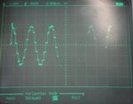
You may have a look on the XY plot I have from the oscilloscope.
XY.jpg
 

Status
Not open for further replies.

Similar threads

Part and Inventory Search

Welcome to EDABoard.com

Sponsor

Back
Top