Continue to Site

Welcome to EDAboard.com

Welcome to our site! EDAboard.com is an international Electronics Discussion Forum focused on EDA software, circuits, schematics, books, theory, papers, asic, pld, 8051, DSP, Network, RF, Analog Design, PCB, Service Manuals... and a whole lot more! To participate you need to register. Registration is free. Click here to register now.

xilinx fir ip core ,and why it has a xxxxx output

Status
Not open for further replies.

hiramlee

Junior Member level 1
Joined
May 15, 2012
Messages
16
Helped
0
Reputation
0
Reaction score
0
Trophy points
1,281
Location
Chengdu,China
Activity points
1,408
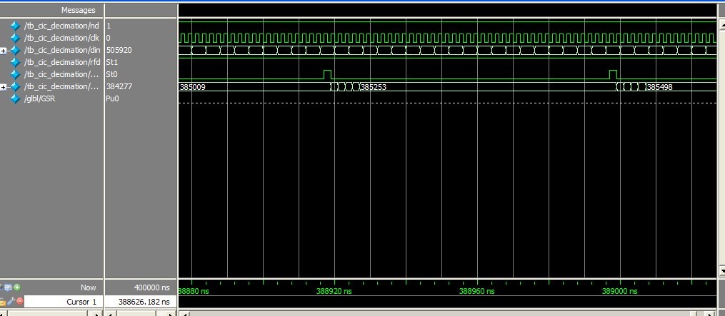
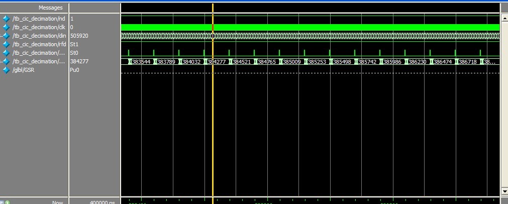
I use the fir core to generate a halfband filter. So, here are the signals :
Code:
//  Instantiate the module
hb unit_hb(
rfd(rfd_hb8_i), 
.rdy(rdy_hb8_i), 
.clk(clk_32_768m), 
.dout(data_hb8_i), 
.din(data_hb_i_inr)
)
//hb 的输入在 rfd置位时,数据要稳定 所以以其下降沿将输入锁存送入
// at the fall edge of rfd,i  put the value of data_cic_i_outr into //register then to the inport
	 always @(negedge rfd_hb8_i)
	      if(reset)
			   data_hb8_i_inr <= 0;
		   else
	        data_hb8_i_inr <= data_cic_i_outr;


but the output dout has a xxxxx value , I'll appreciate it if anyone can help me. many thanks
 

The XXXXX values during simulation usually[i/] you forgot to initialize some values used as input. Also, just guessing, but you may want to assert that reset signal for say 100 ns, and then deassert it. And after that do your thing.

If that doesn't fix things, for a followup post please include testbench code + a screenshot. Makes it easier for the rest of us. :)
 
Many thanks for your help.
The signal mention above is used to make a connection between two component in my project , cic_filter and hb_filter.

To some reason i have to store the result of cic filter and then, wait until it's request by the hb filter.

For the first time ,i used two register and maybe that's lead to the mistake.
Code:
//1st register
always @(posedge rdy_cic_i)
	    if(reset)
		    data_cic_i_outr<=0;
		 else
	   data_cic_i_outr <= data_cic_i;
		
	 cic_decimation unit_cic_i (
		.rfd(rfd_cic_i), 
		.rdy(rdy_cic_i), 
		.nd(clk_32_768m), 
		.clk(clk_32_768m), 
		.dout(data_cic_i), 
		.din(mixer_i[23:4])
//2st register used 
	 always @(posedge rfd_hb8_i)
	      
	        data_hb8_i_inr <= data_cic_i_outr;
hb8 unit_hb8_i(
  .rfd(rfd_hb8_i), 
  .rdy(rdy_hb8_i), 
  .clk(clk_32_768m), 
  .dout(data_hb8_i), 
  .din(data_cic_i_outr)

when i feel puzzled about it and have no idea what to do next. i just delete the latter .
*** know what happen to it and it does work.
 

The handshake signal rfd and rdy are intended to be used in conjunction with the clock, not as clocks itself. Doing so will mess up design timing. But you would probably still get some non "xxxx" output, the point should be corrected but doesn't necessarily cause the problem.

I'm however not sure if you are using the streaming interface correctly, ND has to be wired to handshake signals, connecting CIC ND to a clock isn't correct, set it to '1' or bridge it to RFD if new data is available every clock cycle. FIR ND should be driven by CIC RDY respectively cic_rdy AND fir_nd to take account for the decimation ratio.
 
Thanks a lot.
The signal 'nd' appeared when i change the configuration from nonsymmetric to symmtric.
FIR ND should be driven by CIC RDY respectively cic_rdy
but the rfd_fir are set,,that means it wait for a data input. but at this moment the rdy_cic isn't necessarily set as a result of dfferent latency, so the data to fir may be invalid. That's why i use the register to store the data generated by cic when it's valid ,and then wait to be read by fir.
 
Last edited:

but at this moment the rdy_cic isn't necessarily set as a result of dfferent latency, so the data to fir may be invalid.
I think, you misunderstand the meaning of the handshake signals. Check the timing diagrams in the IP user manuals. No registers are required between the IP blocks.

Outputs are set and inputs are read at clock edges, using the handshake signals as enable. If both blocks are using the same clock, no timining problems are to be expected.

At the CIC output, rdy is set for one clock cycle when valid new data are present. Connecting cic_rdy to fir_nd assures, that each CIC sample is transmitted once to the FIR.
 

Long time since last login.

I have to say the data flow from CIC to HB ,then to FIR have been such a nightmare for me.

i use the CIC .HB and FIR filter in my project of DDC.

the sampling data go through mixer,the to the three filter above.

the word length to cic is 20bits, output data is 20 bits also. that is to say i use 20 bit as the bus length between the connection of the three filter.
cic40.jpgcic40.jpgpfir.jpg
just as the symbol above ,the first is cic filter make a rate of 40 decimation
then hb filter decimate as a rate of 8, then the pfir filter to shape the spectrum.and they are working under the same clock :32.768MHZ.
the data frequency and clock frequency of cic_40 is 32.768MHZ, the HB_8filter receive the data from cic, that is to say the input data frequency is 32.768M/40=819.2k,output data frequency is 102.4hz, the clock of this module is 32.768M,we have mentioned it just now.
the last stage is fir filter.input data is from hb filter .data frequency is 102.4khz and so is the output data frequency.

1 how to resolve the problem of bit growth. and make a truncation 2 how to use handshake signal . i 'm sorry not to understand what you try to say last time.
I'm lookint forward for your reply. and anyone who can give me construction.

MANYTHANKS

- - - Updated - - -

the pict of cic simulation


- - - Updated - - -

This is the signal of three filter
Code:
module cic40 (
  rfd, rdy, nd, clk, dout, din
);
  output rfd;
  output rdy;
  input nd;
  input clk;
  output [19 : 0] dout;
  input [19 : 0] din;

Code:
module hb8 (
  rfd, rdy, nd, clk, dout, din
);
  output rfd;
  output rdy;
  input nd;
  input clk;
  output [19 : 0] dout;
  input [19 : 0] din;

Code:
module pfir (
  rfd, rdy, nd, clk, dout, din
);
  output rfd;
  output rdy;
  input nd;
  input clk;
  output [19 : 0] dout;
  input [19 : 0] din;

- - - Updated - - -

hb filter behavioralhb8_simu2.jpgbh8-simu.jpg simulation

- - - Updated - - -

fir filter behavioral simulation
pfir_simu2.jpgpfir_simulation.jpg
 

Code:
//version1.1 
//使用标准库函数void *memchr(const void *str, int c, size_t n);
#include<stdio.h>
#include<string.h>

#define LEN 80 //maximum of your string

int main()
{
 char string[LEN];

 char ch;
 char * addr;
 printf("please enter a string:\n");
while(gets(string)&&string[0]!='\0')
{
	 
printf("please ener a character:\n");
   ch=getchar();
   
 while((getchar())!='\n');//very important 与输入输出流有关
 addr=memchr(string,ch,strlen(string));
if(NULL!=addr)
  
   printf("The storage address is %d\n",addr- string+1);
else
    printf("not exist!\r\n");

printf("please enter a string , or CTRL+C to quit:\n");
}

return 0;
}
 

Status
Not open for further replies.

Part and Inventory Search

Welcome to EDABoard.com

Sponsor

Back
Top