Knyquist
Newbie level 5

- Joined
- Jan 29, 2012
- Messages
- 9
- Helped
- 0
- Reputation
- 0
- Reaction score
- 0
- Trophy points
- 1,281
- Activity points
- 1,365
Hello!
I'm dealing with the FFT core from Xilinx.
What I would like to do is to take a real signal in input, perform its fft and then reconvert it into a real signal by doing its ifft.
I'm facing a problem regarding the ifft. Actually, even if the output signal from the first fft block is symmetrical (complex conjugate) what I obtain
at the outtput of its ifft is something weird.
The set up is the following:
Radix 2 Burst - Fixed point 19 bit transform with 256 points and natural order output.
Here there are a few graphs to explain what happens. I'm plotting them with matlab because I've set up my vhdl so that to write files with output and input data during the several stages of the transform
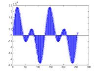
The input signal is formed by the sum of two sinusoids, the first one with two entire periods within 256 samples, the second one with 4 periods. So the input is shown here:
the fft block perform its transformation correctly and at the output i obtain these grapsh for the real part and imaginary part respectively:
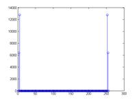
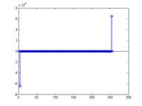
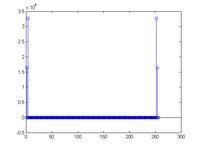
These graphs are correct because peaks are presented at k= 2,4,252,254
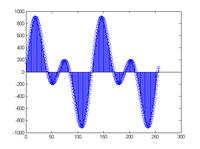
Now, if I take the ifft in matplab of these data what I obtain is exactly the input signal (its real part, the imaginary part is null) (with a scale factor)
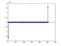
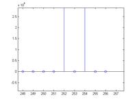
While at the output of the ifft implementation in vhdl I obtain these results for the real part and imaginary part:
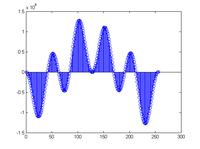
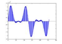
Of course what I would like to obtain is a pure real signal.
A considerations:
- I'm aware about Jim Wu's Blog post about how to get real output from ifft: https://myfpgablog.blogspot.it/2011/04/ifft-with-symmetric-input-in-system.html
My X(0) and X(128) samples from fft are real (I impose them to be real), thus this doesn't work for me. (Or maybe I didn't get the point).
Any help will be welcomed!
Thanks and best regards!
I'm dealing with the FFT core from Xilinx.
What I would like to do is to take a real signal in input, perform its fft and then reconvert it into a real signal by doing its ifft.
I'm facing a problem regarding the ifft. Actually, even if the output signal from the first fft block is symmetrical (complex conjugate) what I obtain
at the outtput of its ifft is something weird.
The set up is the following:
Radix 2 Burst - Fixed point 19 bit transform with 256 points and natural order output.
Here there are a few graphs to explain what happens. I'm plotting them with matlab because I've set up my vhdl so that to write files with output and input data during the several stages of the transform
The input signal is formed by the sum of two sinusoids, the first one with two entire periods within 256 samples, the second one with 4 periods. So the input is shown here:

the fft block perform its transformation correctly and at the output i obtain these grapsh for the real part and imaginary part respectively:


These graphs are correct because peaks are presented at k= 2,4,252,254
Now, if I take the ifft in matplab of these data what I obtain is exactly the input signal (its real part, the imaginary part is null) (with a scale factor)

While at the output of the ifft implementation in vhdl I obtain these results for the real part and imaginary part:


Of course what I would like to obtain is a pure real signal.
A considerations:
- I'm aware about Jim Wu's Blog post about how to get real output from ifft: https://myfpgablog.blogspot.it/2011/04/ifft-with-symmetric-input-in-system.html
My X(0) and X(128) samples from fft are real (I impose them to be real), thus this doesn't work for me. (Or maybe I didn't get the point).
Any help will be welcomed!
Thanks and best regards!

