Continue to Site

Welcome to EDAboard.com

Welcome to our site! EDAboard.com is an international Electronics Discussion Forum focused on EDA software, circuits, schematics, books, theory, papers, asic, pld, 8051, DSP, Network, RF, Analog Design, PCB, Service Manuals... and a whole lot more! To participate you need to register. Registration is free. Click here to register now.

[SOLVED] x marks the spot, but where?

Status
Not open for further replies.

d123

Advanced Member level 5
Joined
Jun 7, 2015
Messages
2,505
Helped
494
Reputation
992
Reaction score
525
Trophy points
1,393
Location
Spain
Activity points
27,148
Hi,

Breaking no new ground with this one. Another member's thread about a latching off-delay circuit for a relay got me thinking about latching BJT or MOSFET circuits...

I've seen a nice-looking single pushbutton one that only uses an NMOS and a PMOS to latch on and off instantly and I know there are plenty of similar variations on this theme...

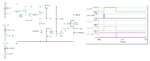
Anyway, messing around this afternoon, I came up with this non-contribution to the advancement of humankind:

Latch on off discrete bjts.JPG


I was flummoxed as to how to add an off-delay to this circuit limiting myself to just using a capacitor and a resistor, and another BJT, diode, etc. if need be.

The question really is just 'academic', I'm unlikely to ever make this, I assume.., but never say never, so purely along the lines of oompa loompa doompety doo, I've got a perfect puzzle for you - what could be done to add an off-delay to this circuit using only basic components (no timer ICs, etc.)?

Thanks.
 

Attachments

  • Latch on off discrete bjts.JPG
    Latch on off discrete bjts.JPG
    84.4 KB · Views: 162

A simple pulse extender can be made with a diode-capacitor-resistor network. Configure it to sample and hold.
To obtain longer delay from the capacitor draining, feed its voltage to a transistor or logic gate.
 
  • Like
Reactions: d123

    d123

    Points: 2
    Helpful Answer Positive Rating
Hi,

Just to finish off this thread, the below schematic is the final adjustable on- and off-delay latch circuit. In a sense, a bit of a glorified 555 in some ways...

I had to admit defeat of only using BJTs, resistors, capacitors and diodes because the ~600 mV base turn on voltage of the BJTs that were replaced by the comparators gave little timing flexibility and limitingly short on- and off-delays, and resetting the RC capacitor proved very hard to obtain an adequate signal for the draining NPNs.

The BJT-only version was time-limited, messy and imperfect. The comparator (+ NOT gate) version can be configured from milliseconds to hundreds of seconds of on- and off-delay, has neat signals and while no doubt not perfect by a long shot, functions correctly.

Circuit operation:

Top latch is latched by a brief high-going pulse (ON) in order to charge the on-delay RC and be released/turn off when the top comparator senses 2/3 Vcc, at that moment the right-hand latch latches on and powers the load.

Bottom latch is the same as the ON latch - it is latched by a brief high-going pulse (OFF) in order to charge the off-delay RC and be released when the bottom comparator senses, yet again, 2/3 Vcc. At that moment, the load latch is turned off by a low-going pulse to the left-hand PNP, which sends a high pulse to the base of the right-hand PNP, turning the load latch off.

The respective capacitor-draining NPNs are to speed up the re-triggering of either delay section and prevent the signals overlapping with long charging times.

If I remove the charging capacitors, the simulation goes very slowly at the ON moment - usually a bad sign of comparator chattering or similar undesired events. I originally monitored about 18 different signals, comparator outputs included, so will look into that at next opportunity I have. Maybe it needs a minimum RC with a tiny capacitor, e.g. 10 nF, so the comparator inputs don't rise too quickly, who knows, keen to see reason for simulation slowdown as other signals looked correct and without chatter.

Hopefully, the rest if how it functions is even more evident.

I know it's a bit silly, but I just wanted to put together an on- and off-delay latching circuit using my own mind and not just copying something already done.

LATCH ON OFF DISCRETE BJTS V9 COMPARATOR WITH RC CAPACITOR DRAIN.JPG
 

Real fine.

I too like to do these kinds of experiments and explorations.
We gain insights into handy methods for by which simple components do this or that task.
 
  • Like
Reactions: d123

    d123

    Points: 2
    Helpful Answer Positive Rating
Hi Brad,

I agree. Technical knowledge is important, first and foremost, but learning by exploration and (sensible/safe) experimentation can bring up unexpected and insightful aspects of circuit and component behaviours.
--- Updated ---

Well, that's as far as this design goes unless I can ever get back into a house with a normal electricity supply (and that has an outdoor area for my asthmatic cat and my sporty cat): an adjustable on- and off-delay latch with reset.

The load latch is good alone for no delays, the delay circuits appear to operate correctly down to 1uF. Changing the BJTs to other BJTs or MOSFETs means altering some resistor values, from what I saw.

It was fun to explore and learn a few things from.

LATCH ON OFF DISCRETE BJTS V10 CAPACITOR DRAIN AND RESET.JPG
 
Last edited:

The real test of a circuit like this is power on/off not producing false transients.

Also accuracy over T and V of pulse timing. The LM555 is kind of awful on this.

All above one of the reasons for today's processors, most take care of these issues.


Regards, Dana.
 
Last edited:
  • Like
Reactions: d123

    d123

    Points: 2
    Helpful Answer Positive Rating
Hi Dana,

The real test of a circuit like this is power on/off not producing false transients.

I couldn't agree more. And, a simulation is just that - a mathematical representation of a potential reality.

Also accuracy over T and V of pulse timing. The LM555 is kind of awful on this.

I couldn't agree more. A capacitor is a very loose clock element.

Ahh, the 555 may be what it is, but it is a historical gem and still a very handy part for skilled and unskilled alike where precision is not of paramount importance. I would have liked to meet Hans and ask him how he worked through the original design.

All above one of the reasons for today's processors, most take care of these issues.

I agree but not entirely, while processors have taken a lot of the misery of having to accept second-best inaccuracy and expansively unwieldy PCB real estate out of circuit design, sometimes an Mcu can be overkill, and I find disppointing the base-level learning gap a dependence on code creates, a resistor is never just a resistor, a capacitor is many things to many people, depending on its use in-circuit...

Thanks for your input, valid comments always valued.
 

Status
Not open for further replies.

Part and Inventory Search

Welcome to EDABoard.com

Sponsor

Back
Top