Continue to Site

Welcome to EDAboard.com

Welcome to our site! EDAboard.com is an international Electronics Discussion Forum focused on EDA software, circuits, schematics, books, theory, papers, asic, pld, 8051, DSP, Network, RF, Analog Design, PCB, Service Manuals... and a whole lot more! To participate you need to register. Registration is free. Click here to register now.

Wireless accelerometer with HT12E and HT12D

Status
Not open for further replies.

pratik069

Junior Member level 2
Joined
Aug 4, 2008
Messages
20
Helped
1
Reputation
2
Reaction score
1
Trophy points
1,283
Activity points
1,397
Hello everyone,
i have a wireless robot with 434 mhz frequency and HT12E and HT 12D as encoder and decoder respectively.
i want to control my robot using 2 axes accelerometer in forward, reverse, left and right directions.

I'm facing problem interfacing accelerometer with this circuit as i just have two inputs X and Y[from accelerometer] that i can give my encoder. can any one suggest me some IC that can detect variation of X above 1.65 volts and below 1.65 volts, so that it acts as 2 different inputs.

Please help!!!!
 

Make use of the comparator IC's available in the market, Input to the Vref or V+ shud be 1.65V or desired and V- will be from accelerometer so finally the output of the comparator will be HIGH or LOW [1 or 0]..


Hope it helps you :)
 

Thank you for the reply Santosh.

Even i had thought of using a comparator but i'm not able to figure out how do i split the linear output from accelerometer [i.e. 0.8V to 2.8V] into two [i.e. from 0.8V to 1.65V and 1.66V to 2.8 V].

I need a circuit which can split the outputs X and Y into four so that it can be used to control my robot in different directions
 

Ya gt it Pratik,
Its pretty simple same concept. Use dual opamp IC's i.e dual comparators single IC. The output of your accelerometer is given as input to both the V- (literally shorted) and Vref/V+ of 1st comparator is 1v approx and 2nd comparator is 1.6V approx. So the operations goes like this, If the output is aroumd 1V you get an HIGH at 1st Comparator, If its more than 1.6V you get an HIGH at 2nd Comparator.

Hope it works in your appln... :)
 

I tried implementing to split the X and Y outputs using two comparator IC [LM358]. But the output wasn't satisfactory. Can anyone suggest some other circuit to get the output as i had mentioned before. Do i need to use ADC?
 

Thank you for the reply amol. Actually i already have a transmitter n receiver as mentioned earlier and i don't want to make the transmitter circuit complex as it would be mounted on the palm.

I have not used PIC yet so would prefer 89v51. The link provided was quite informative. Would try interfacing ADC with 89V51. But the the task is achieve without programming it would be better.
 

I tried implementing to split the X and Y outputs using two comparator IC [LM358]. But the output wasn't satisfactory. Can anyone suggest some other circuit to get the output as i had mentioned before. Do i need to use ADC?

Can you be more clear in your statement. What was the input & output.
 

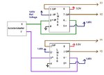
Splitter Circuit.JPG

This is a rough circuit which i had used.
 

Status
Not open for further replies.

Similar threads

Part and Inventory Search

Welcome to EDABoard.com

Sponsor

Back
Top