Continue to Site

Welcome to EDAboard.com

Welcome to our site! EDAboard.com is an international Electronics Discussion Forum focused on EDA software, circuits, schematics, books, theory, papers, asic, pld, 8051, DSP, Network, RF, Analog Design, PCB, Service Manuals... and a whole lot more! To participate you need to register. Registration is free. Click here to register now.

Will this design work as a split supply for an op-amp circuit?

Status
Not open for further replies.

trevorg

Newbie level 4
Joined
Feb 24, 2014
Messages
7
Helped
0
Reputation
0
Reaction score
0
Trophy points
1
Activity points
91
Hi guys,

First post here. I'm just getting into audio amps, plan to build myself a chip amp eventually.

I've been looking at different headphone amp designs using op amps and I've been particularly interested in supply splitting. The basic resistor divider + big caps method seems quite common, but can cause DC offset issues due to loading. I've also seen complimentary regulator designs with 78xx+79xx+reference voltage, but people have noticed potential instability issues.

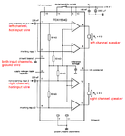
I'd like to design one with BJT's and I've come up with a simple design that works in my mind but I'm seeking potential problems and suggestions from others.

schemeit-project.png

The transistors are biased always-on in common collector topology with each one allowing current to flow in one direction. The 2Ohm resistors are there to dissipate the energy from the transistor output variations. I figure capacitors should be added from ground to each rail to smooth bumps but I left it out.

Will this design work as a split supply for an op-amp circuit?
 

It will work but I'm not sure it would be any better than the other methods you mentioned. You would almost certainly not have an equally divided supply because of the different transistor types and the maximum current you could draw would be quite small as it has no feedback method to 'track' the center voltage. I doubt it would work as well as two Zener diodes in series across the 10V. If it has to be regulated, there is no reason why normal voltage regulators should be unstable as long as you follow the manufacturers capacitor recommendations.

A better method would be to use an op-amp with it's non-inverting input held at half supply voltage with two equal valued resistors. You can then use it to drive the transistors with feedback from their output back to the inverting input. It would accurately divide the voltage and make it immune from supply voltage variations and to some extent the current drawn from it. The configuration would be similar to the classic op-amp audio driver but instead of audio signal feeding it, you give it half the supply voltage from the potential divider.

Brian.
 
Why do you need to split the battery into two rails? Audio has no frequencies near DC.
Simply bias the audio amp so that its output is at half the supply voltage and use a series output coupling capacitor like billions of excellent audio amps do.
 

As AG noted, you don't normally need (or want) a split supply for audio amps. A split supply is only required if you want to pass a DC or very low frequency signal.
 

It will work but I'm not sure it would be any better than the other methods you mentioned. You would almost certainly not have an equally divided supply because of the different transistor types and the maximum current you could draw would be quite small as it has no feedback method to 'track' the center voltage. I doubt it would work as well as two Zener diodes in series across the 10V. If it has to be regulated, there is no reason why normal voltage regulators should be unstable as long as you follow the manufacturers capacitor recommendations.


Brian, it's not super important that the virtual ground sits exactly half way between 10V and 0V, just as long as it's stable. I thought this circuit would be better than a simple divider because only a fraction of the load is going through the resistor divider so the base voltages won't fluctuate as much.

How would I go about introducing feedback? Would it be a large resistor between the base of one transistor to the emitter of the other transistor?
 

If two resistors bias the input of an audio amplifier at half the supply voltage then the bias voltage is as stable as the power supply voltage, NO load current goes through the divider. A filter capacitor and a zener diode can be used for even more stability.
 

I didn't come here asking about single supply op amp design so please stop telling me to use a single supply design. I am working on a direct-coupled design so a virtual ground is required.

I posted here to get feedback on my rail splitter, as my post title suggests, I am aware of single supply op amp configurations but I am just trying to experiment with different circuits.
 

Frequently an opamp is used as a rail splitter. Then the output impedance of the entire amplifier circuit is twice the impedance of a single-supply amplifier but with headphones as the load it doesn't matter. But if the headphones are low impedance then the amplifier and the rail splitter both need to be able to supply the load current.
 
I posted here to get feedback on my rail splitter....
Indeed.:) The basic idea is good, certainly better than a simple resistive divider.

There is one detail I'd change though - I wouldn't use separate resistive dividers to bias the two transistor bases. Starting with your circuit, what I would do is to remove the two 1K resistors and add "something" between the transistor bases instead.

If the supply voltage is well regulated or known to be constant then the "something" could just be a resistor. However, if the supply voltage is variable (e.g. a battery that drops from 9V when new to 7V at end of life), then I would want to use something that keeps the bias voltage between the bases fairly constant when the supply voltage varies.

One option is to use two or three diodes connected in series. Another nice option is to use a cheap red LED. They make surprisingly good voltage references (better than most low-voltage Zeners), and it would serve as a power indicator as well.

I agree it's a good idea to put large capacitors between the virtual ground and each of the supply rails. They won't do anything useful at DC or very low frequencies, but at higher frequencies they'll pass most of the current, making life easier for the transistors. They'll also minimise the voltage swing between the supply rails and the virtual ground at higher frequencies.
 
I'm running a simulation of your post #1 schematic. It works pretty much as you intended. However it does require increased current draw from your 10V supply.


An audio signal means only the positive or negative load is active at any one time. In the same way my loads are lopsided in the screenshot.
 

Indeed.:) The basic idea is good, certainly better than a simple resistive divider.

There is one detail I'd change though - I wouldn't use separate resistive dividers to bias the two transistor bases. Starting with your circuit, what I would do is to remove the two 1K resistors and add "something" between the transistor bases instead.

Thanks godfreyl. The reason I've used two dividers is so I can get the base voltages just right (a difference of 1.4V between bases) so each one has 5V at it's emitter, minimizing imbalance and saving energy.

I tested my circuit today on breadboard. With a decent load on either rail the circuit current gradually goes up over time. I noticed the base-emitter voltage was decreasing for whichever transistor was loaded (I suspect due to heating), pulling its emitter voltage closer to its base voltage which caused imbalance at the emitters. I figure eventually the base-emitter voltage would settle for a given temp rise but the circuit would be terribly inefficient by this stage.

Bradtherad, I suspect your simulation didn't produce these thermal problems with the transistors?

So realizing I needed some feedback to prevent the thermal runaway, I implemented the following solution:
schemeit-project(1).png

Now I know that this isn't a discrete circuit anymore, and I'm aware that there are hi power op amps available, but the op amp here can be any basic and cheap one with a good slew rate. I used an LF412 which worked okay. With a gain of ~750 in the transistors the op amps don't need to supply much current.

I breadboarded the circuit and I was fairly impressed with it. The BD68x's are what I had laying around and performed fine with a 40Ohm load. The virtual ground sat at exactly 5V unloaded and the circuit drew ~15mA. When I connected 40Ohms from the +10V to the virtual ground, the virtual ground voltage was about 5.08V (123mA through resistor) and I noticed the left op amp was putting out 1.5V (maximum swing for LF412) as it tried to turn Q1 off. Q1 was hard off at this stage, perhaps a bit of leakage, and the Vbe was -3.5V. Most transistors have a maximum Veb rating of 5V and I think they can act like a zener after this stage? If I was splitting a 20V supply I could run into trouble but adding a diode between the op amp output and transistor base would fix this.

Now one thing I noticed with the circuit that I'm hoping I can get help with is that the difference between the inputs of the left op amp - 50mV - was always greater than the input difference of the right op amp - 0.02mV - when either rail is loaded heavily. I changed the op amps with different ones and the same thing occurred. I suspect it might be that the op amp is better at sinking than sourcing, or it could be that the transistors aren't perfect complements. What do you think?
 
Last edited:

Your new attachment does not work maybe because it is a PHP file and maybe this website (and I) do not know this file type. Please post it as a normal schematic file type like a PNG.
 

In the past, I've used the TLE2426 precision virtual ground IC from Texas Instruments.

It can sink/source 20 mA. With an external NPN/PNP pair its output current can be further increased.

- - - Updated - - -

I also attempted to open the file, but cannot read a PHP. So I cannot comment on your circuit.
 

I've added the image to my previous post and here it is again:
schemeit-project(1).png
 

A thought crossed my mind today regarding the latest circuit I uploaded - would this opamp driven transistor topology work for an audio amp? What I'm think is you could have two non-inverting op amps driving complementary BJT's with common emitters (just like the circuit) for one side of a speaker. For the other side of the speaker we feed the same audio signal to two inverting op amps and drive two complementary BJT's in the same fashion (I think this is called bridge-tied-load?). No AC coupling capacitor would be required at the load as the non-inverted and inverted signal cancel out the DC. People might be thinking that this is just like push-pull Class B with feedback, but that is not so because each transistor is driven by a separate op amp so crossover shouldn't be as much of a problem. As long as each identical op amps are used with identical gains and input impedance, synchronization shouldn't be an issue either?

What do you guys think? I'm just trying to experiment with different audio circuits.

Yes, bridging two op amps would probably be optimum, for both loudness and efficiency. It is like making an H-bridge (a common topology).

Example found at:

**broken link removed**

9424362400_1393552757.gif
 

A "bridge-tied-load" amplifier is common for car radios because it effectively almost doubles the voltage swing across a speaker which also almost doubles the current in the speaker so the output power is about 3.5 times as much as with a single amplifier. It also eliminates the output coupling capacitor.

Here is a cheap old (maybe not made anymore) car radio bridged stereo amplifier IC:
 

Attachments

  • tda1554.png
    tda1554.png
    26.4 KB · Views: 114

Status
Not open for further replies.

Similar threads

Part and Inventory Search

Welcome to EDABoard.com

Sponsor

Back
Top