Continue to Site

Welcome to EDAboard.com

Welcome to our site! EDAboard.com is an international Electronics Discussion Forum focused on EDA software, circuits, schematics, books, theory, papers, asic, pld, 8051, DSP, Network, RF, Analog Design, PCB, Service Manuals... and a whole lot more! To participate you need to register. Registration is free. Click here to register now.

wilkinson splitter loss

Status
Not open for further replies.

yuvalkesi

Member level 5
Joined
May 13, 2009
Messages
92
Helped
0
Reputation
0
Reaction score
0
Trophy points
1,286
Activity points
2,036
Hi,
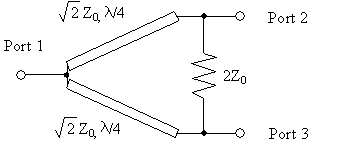
A simple basic question.. What is the loss when going thru a wilkinson power divider?
I think it's 3dB (because the power splits by 2), but someone told me it's not correct and it's about 7dB... I don't understand why.
Thanks guys,
Tom
 

Hi

I think you mix loss and power split. The Wilkinson divider split the power between its two ports by half(3 dB). So if you send in 0 dBm(1mW) you will get -3dBm(0.5dBm) at each output. This is no loss because you still have the same amount of power available, now just at two ports.
The loss comes from the copper and dielectric material used. This just means you have to add a little something extra to the 3 dB.
 

Ok!
Thanks. It makes sense now.
Just the last sentence was a bit blurry... What do you mean by: This just means you have to add a little something extra to the 3 dB
You wrote 3dB is no loss, but later you said to add extra to this 3dB. Didn't understand that...
In my design, I'm using the wilkinson divider as a 'junction' for tx or rx path. When it's tx path (or rx path) only 2 legs out of the 3 of the divider are used. Each time (rx or tx) different legs are used. What is the loss in this case?

Thanks.
 

In my design, I'm using the wilkinson divider as a 'junction' for tx or rx path.

Why do you do that? Even with an "ideal" wilkinson divider, you will loose 3dB in TX and 3dB in RX direction. In TX mode, half of the power is lost in the resistor. In RX mode, half of the power is lost because it goes to the TX path.
 

(Note: it's a working product with no intention to change the design)
Ok, now you made me confused! tyassin talked about splitting with no loss (except dialectric losses), you do talk about loss on the resistor. tyassin never mentioned loss on the resistor...
Please explain...
Tom
 

Well this is because when you use one of the outputs as an input half the power is going to the formal input and half is going into the isolation resistor.
 

I was talking about both directions of the signal flow.

51_1325844280.png


From port 1 to ports 2/3, the "loss" is 3dB because the power is split between these two ports.
From port 2/3 to port 1, the loss is also 3dB. Half of the power is lost in the resistor and only half of the power is available at port 1.
 

Yes, typically Volker is correct, if you add another 0.2 dB or so for circuit losses.

But there are other scenarios.

There is a "resistive" power splitter. It is composed of 3 resistors in a star or delta--no transmission lines involved. That has maybe 6.3 dB of loss.

Also, for the wilkenson splitter, you can use it like a power combiner with 0 dB loss. Say you have a signal that you input to the splitter. The 2 outputs are 3 dB down. Then you pass both of the signal thru some RF circuit (say a shunt varactor diode with no loss but some phase shift). The 2 signals then arrive (both with the same phase shift) to a 2nd wilkenson. They recombine with NO loss vectorially at the wilkenson output. This is because the 2 signals in either wilkenson are IN PHASE, so no current flows thru the resistors.
 

Ok,
Got it.
Thank you all for your help. Much appreciated!
 

I think, the answer is simple. The only options for an (ideally) lossless Rx/Tx diplexer are either a switch or a circulator, presumed Rx and Tx are using the same frequency.
 

Status
Not open for further replies.

Part and Inventory Search

Welcome to EDABoard.com

Sponsor

Back
Top