wangmengde
Newbie level 5
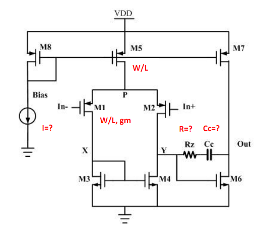
I try to design a two stage opamp according to the following picture:
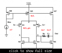
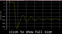
The Rz I used is 5.6k. I tried to used a MOSFET in linear region to take the place of Rz to save some area. I used Hspice to test that when MOSFET is used the Hole and Zero are in the same place as resistor is used. But When connect this OPAMP in negative feedback pattern with gain=-10, the unit step response becomes oscillating as follows, which does not occur when real resistor is used:
in this simulation : Vdd-Vss=3.3v Common mode ground=1.65v the input step is from 1.65v to 1.75v and is feed into the negative input port.
I do not know why this is the case and hope someone can give me some clues or explanations.
The Rz I used is 5.6k. I tried to used a MOSFET in linear region to take the place of Rz to save some area. I used Hspice to test that when MOSFET is used the Hole and Zero are in the same place as resistor is used. But When connect this OPAMP in negative feedback pattern with gain=-10, the unit step response becomes oscillating as follows, which does not occur when real resistor is used:

in this simulation : Vdd-Vss=3.3v Common mode ground=1.65v the input step is from 1.65v to 1.75v and is feed into the negative input port.
I do not know why this is the case and hope someone can give me some clues or explanations.