Continue to Site
Follow along with the video below to see how to install our site as a web app on your home screen.
Note: This feature may not be available in some browsers.
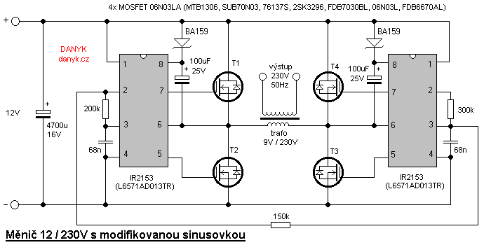
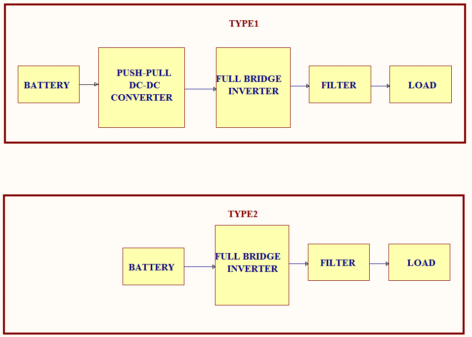
The first one is having transformer at the push-pull dc to dc converter. Type 2 has transformer at full bridge inverter...
I hope the first one is best suitable for solar system, because the variable DC from the solar is easily adjustable (regulated) by using DC-DC converter, but your thought is totally different???:shock:
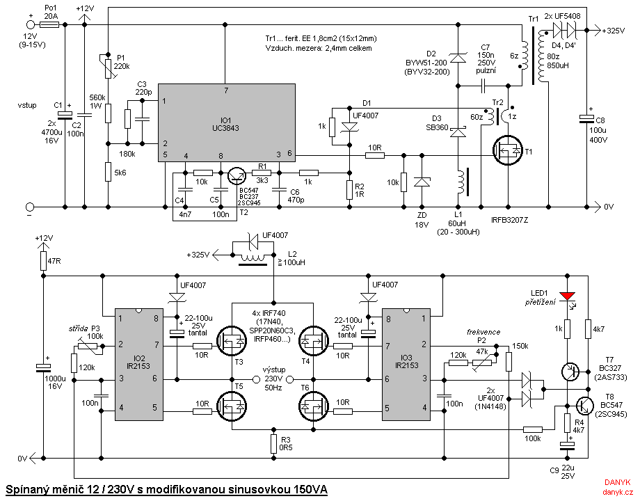

but in second method we need to use t/f at full bridge side with required load freq may b low - 50/60Hz. this maximizes the size and weight of the inv due to big low freq laminated core t/f