Continue to Site

Welcome to EDAboard.com

Welcome to our site! EDAboard.com is an international Electronics Discussion Forum focused on EDA software, circuits, schematics, books, theory, papers, asic, pld, 8051, DSP, Network, RF, Analog Design, PCB, Service Manuals... and a whole lot more! To participate you need to register. Registration is free. Click here to register now.

Why this is not working ?

Status
Not open for further replies.
@FvM

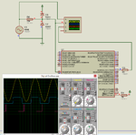
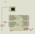
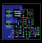
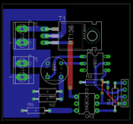
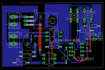
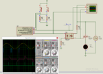
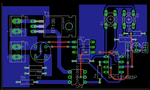
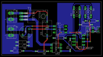
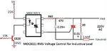
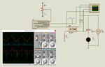
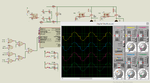
I have fixed the opto circuit. Here is fixed circuit.


Edit:

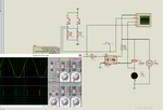
Changed the code a little but still not working.


Code C - [expand]
1
2
3
4
5
6
7
8
9
10
11
12
13
14
15
16
17
18
19
20
21
22
23
24
25
26
27
28
29
30
31
32
33
34
35
36
37
38
39
40
41
42
43
44
45
46
47
48
49
50
51
52
53
54
55
56
57
58
59
60
61
62
63
64
65
66
67
68
69
70
71
72
73
74
75
76
77
78
79
80
81
82
83
84
85
86
87
88
89
90
91
92
93
94
95
96
97
98
99
100
101
102
103
104
105
106
107
108
109
110
111
112
113
114
115
116
117
118
119
120
121
122
123
124
125
126
127
128
129
130
131
132
133
134
135
136
137
138
139
140
141
142
143
144
145
146
147
148
149
150
151
152
153
154
155
156
157
158
159
160
161
162
163
164
165
166
167
168
169
170
171
172
173
174
175
176
177
178
179
180
181
char milliSec[4] = {0, 0, 0, 0}, i = 0, max_ = 0, initial = 0, readKeys = 0;
 
sbit Gate1_Trigger at LATD0_bit;
sbit Gate1_Trigger_Direction at TRISD0_bit;
 
sbit Gate2_Trigger at LATD1_bit;
sbit Gate2_Trigger_Direction at TRISD1_bit;
 
sbit Gate3_Trigger at LATD2_bit;
sbit Gate3_Trigger_Direction at TRISD2_bit;
 
sbit Gate4_Trigger at LATD3_bit;
sbit Gate4_Trigger_Direction at TRISD3_bit;
 
//Timer1
//Prescaler 1:1; TMR1 Preload = 63536; Actual Interrupt Time : 1 ms
 
//Place/Copy this part in declaration section
void InitTimer1() {
    T1CON = 0x01;
    TMR1IF_bit = 0;
    TMR1H = 0xF8;
    TMR1L = 0x30;
    TMR1IE_bit = 1;
}
 
void InitTimer1Initial() {
    T1CON = 0x01;
    TMR1IF_bit = 0;
    TMR1H = 0xFE;
    TMR1L = 0xFF;
    TMR1IE_bit = 1;
}
 
void interrupt() {
 
     if(INT0IF_bit) {
        i = 0;
        if(milliSec[0] == 0)              //if any of milliSec[x] is 0 then fire the corresponding triac immediately after ZC.
             Gate1_Trigger = 1;
        if(milliSec[1] == 0)
             Gate2_Trigger = 1;
        if(milliSec[2] == 0)
             Gate3_Trigger = 1;
        if(milliSec[3] == 0)
             Gate4_Trigger = 1;
        
        InitTimer1();                    //Start 1 ms timer interrupt
        
        Delay_us(100);
        Gate1_Trigger = 0;
        Gate2_Trigger = 0;
        Gate3_Trigger = 0;
        Gate4_Trigger = 0;
        
        INT0IF_bit = 0;
     }
     
     if(TMR1IF_bit) {
     
          if(i == (milliSec[0]))
              Gate1_Trigger = 1;
 
          if(i == (milliSec[1]))
              Gate2_Trigger = 1;
 
          if(i == (milliSec[2]))
              Gate3_Trigger = 1;
 
          if(i == (milliSec[3]))
              Gate4_Trigger = 1;
 
          Delay_us(100);
          Gate1_Trigger = 0;
          Gate2_Trigger = 0;
          Gate3_Trigger = 0;
          Gate4_Trigger = 0;
          
          if(i == max_)TMR1ON_bit = 0;
          
          ++i;
          
          TMR1IF_bit = 0;        // 1ms Timer interrupt
          TMR1H = 0xF8;
          TMR1L = 0x30;
     }
     
     if(INT1IF_bit) {
          readKeys = 1;
          INT1IF_bit = 0;
     }
}
 
void main() {
 
     CM1CON0 = 0x00;
     CM2CON0 = 0x00;
     
     ANSELA = 0x00;
     ANSELB = 0x00;
     ANSELC = 0x00;
     ANSELD = 0x00;
     ANSELE = 0x00;
 
     TRISA = 0xC0;
     TRISB = 0x03;
     TRISC = 0xFF;
     TRISD = 0x00;
     TRISE = 0x08;
 
     PORTA = 0x00;
     PORTB = 0x00;
     PORTC = 0x00;
     PORTD = 0x00;
     PORTE = 0x08;
 
     LATA = 0x00;
     LATB = 0x00;
     LATC = 0xFF;
     LATD = 0x00;
     LATE = 0x00;
 
     Gate1_Trigger_Direction = 0;
     Gate2_Trigger_Direction = 0;
     Gate3_Trigger_Direction = 0;
     Gate4_Trigger_Direction = 0;
 
     Gate1_Trigger = 0;
     Gate2_Trigger = 0;
     Gate3_Trigger = 0;
     Gate4_Trigger = 0;
 
     INTEDG0_bit = 0;
     INT0IF_bit = 0;
     INT0IE_bit = 1;
     
     INTEDG1_bit = 1;
     INT1IF_bit = 0;
     INT1IE_bit = 1;
     
     PEIE_bit = 1;
     GIE_bit = 1;
 
     while (1) {
 
            if(milliSec[0] > milliSec[1])max_ = milliSec[0];
            else max_ = milliSec[1];
            
            if(milliSec[1] > milliSec[2])max_ = milliSec[1];
            else max_ = milliSec[2];
            
            if(milliSec[2] > milliSec[3])max_ = milliSec[2];
            else max_ = milliSec[3];
            
            if(milliSec[3] > milliSec[4])max_ = milliSec[3];
            else max_ = milliSec[4];
            
            if(readKeys) {
                 Delay_ms(50);
                 
                 if(PORTC == 0x01)
                        if(milliSec[0] < 9)++milliSec[0];
                 else if(PORTC == 0x02)
                        if(milliSec[0] > 0)--milliSec[0];
                 else if(PORTC == 0x04)
                        if(milliSec[1] < 9)++milliSec[1];
                 else if(PORTC == 0x08)
                        if(milliSec[1] > 0)--milliSec[1];
                 else if(PORTC == 0x10)
                        if(milliSec[2] < 9)++milliSec[2];
                 else if(PORTC == 0x20)
                        if(milliSec[2] > 0)--milliSec[2];
                 else if(PORTC == 0x40)
                        if(milliSec[3] < 9)++milliSec[3];
                 else if(PORTC == 0x80)
                        if(milliSec[3] > 0)--milliSec[3];
                        
                 readKeys = 0;
            }
     }
}


- - - Updated - - -

New code but the buttons not yet working.


Code C - [expand]
1
2
3
4
5
6
7
8
9
10
11
12
13
14
15
16
17
18
19
20
21
22
23
24
25
26
27
28
29
30
31
32
33
34
35
36
37
38
39
40
41
42
43
44
45
46
47
48
49
50
51
52
53
54
55
56
57
58
59
60
61
62
63
64
65
66
67
68
69
70
71
72
73
74
75
76
77
78
79
80
81
82
83
84
85
86
87
88
89
90
91
92
93
94
95
96
97
98
99
100
101
102
103
104
105
106
107
108
109
110
111
112
113
114
115
116
117
118
119
120
121
122
123
124
125
126
127
128
129
130
131
132
133
134
135
136
137
138
139
140
141
142
143
144
145
146
147
148
149
150
151
152
153
154
155
156
157
158
159
160
161
162
163
164
165
166
167
168
169
170
171
172
173
char milliSec[4] = {0, 0, 0, 0}, i = 0, max_ = 0, readKeys = 0;
 
sbit Gate1_Trigger at LATD0_bit;
sbit Gate1_Trigger_Direction at TRISD0_bit;
 
sbit Gate2_Trigger at LATD1_bit;
sbit Gate2_Trigger_Direction at TRISD1_bit;
 
sbit Gate3_Trigger at LATD2_bit;
sbit Gate3_Trigger_Direction at TRISD2_bit;
 
sbit Gate4_Trigger at LATD3_bit;
sbit Gate4_Trigger_Direction at TRISD3_bit;
 
//Timer1
//Prescaler 1:1; TMR1 Preload = 63536; Actual Interrupt Time : 1 ms
 
//Place/Copy this part in declaration section
void InitTimer1() {
    T1CON = 0x01;
    TMR1IF_bit = 0;
    TMR1H = 0xF8;
    TMR1L = 0x30;
    TMR1IE_bit = 1;
}
 
void interrupt() {
 
     if(INT0IF_bit) {
        i = 0;
        if(milliSec[0] == 0)              //if any of milliSec[x] is 0 then fire the corresponding triac immediately after ZC.
             Gate1_Trigger = 1;           //These 4 if statements will take some 15 us to execute
        if(milliSec[1] == 0)
             Gate2_Trigger = 1;
        if(milliSec[2] == 0)
             Gate3_Trigger = 1;
        if(milliSec[3] == 0)
             Gate4_Trigger = 1;
        
        InitTimer1();                    //Start 1 ms timer interrupt
        
        Delay_us(100);                   //Timer will be running and before 1 ms expires the below code which requires some 15 us will execute
        Gate1_Trigger = 0;
        Gate2_Trigger = 0;
        Gate3_Trigger = 0;
        Gate4_Trigger = 0;
        
        INT0IF_bit = 0;
     }
     
     if(TMR1IF_bit) {
     
          if(i == (milliSec[0]))            //These 4 if statements will take some 15 us to execute
              Gate1_Trigger = 1;
 
          if(i == (milliSec[1]))
              Gate2_Trigger = 1;
 
          if(i == (milliSec[2]))
              Gate3_Trigger = 1;
 
          if(i == (milliSec[3]))
              Gate4_Trigger = 1;
 
          Delay_us(100);
          Gate1_Trigger = 0;
          Gate2_Trigger = 0;
          Gate3_Trigger = 0;
          Gate4_Trigger = 0;
          
          if(i == max_)TMR1ON_bit = 0;
          
          ++i;
          
          TMR1IF_bit = 0;        // 1ms Timer interrupt
          TMR1H = 0xF8;
          TMR1L = 0x30;
     }
     
     if(INT1IF_bit) {
          readKeys = 1;
          INT1IF_bit = 0;
     }
}
 
void main() {
 
     CM1CON0 = 0x00;
     CM2CON0 = 0x00;
     
     ANSELA = 0x00;
     ANSELB = 0x00;
     ANSELC = 0x00;
     ANSELD = 0x00;
     ANSELE = 0x00;
 
     TRISA = 0xC0;
     TRISB = 0x03;
     TRISC = 0xFF;
     TRISD = 0x00;
     TRISE = 0x08;
 
     PORTA = 0x00;
     PORTB = 0x00;
     PORTC = 0x00;
     PORTD = 0x00;
     PORTE = 0x08;
 
     LATA = 0x00;
     LATB = 0x00;
     LATC = 0xFF;
     LATD = 0x00;
     LATE = 0x00;
 
     Gate1_Trigger_Direction = 0;
     Gate2_Trigger_Direction = 0;
     Gate3_Trigger_Direction = 0;
     Gate4_Trigger_Direction = 0;
 
     Gate1_Trigger = 0;
     Gate2_Trigger = 0;
     Gate3_Trigger = 0;
     Gate4_Trigger = 0;
 
     INTEDG0_bit = 0;
     INT0IF_bit = 0;
     INT0IE_bit = 1;
     
     INTEDG1_bit = 1;
     INT1IF_bit = 0;
     INT1IE_bit = 1;
     
     PEIE_bit = 1;
     GIE_bit = 1;
 
     while (1) {
 
            if(milliSec[0] > milliSec[1])max_ = milliSec[0];             //These 4 if statements take some 5 us to execute
            else max_ = milliSec[1];
            
            if(milliSec[1] > milliSec[2])max_ = milliSec[1];
            else max_ = milliSec[2];
            
            if(milliSec[2] > milliSec[3])max_ = milliSec[2];
            else max_ = milliSec[3];
            
            if(milliSec[3] > milliSec[4])max_ = milliSec[3];
            else max_ = milliSec[4];
            
            if(readKeys) {
                 Delay_ms(50);           //Debounce delay for button press
                 
                 if(PORTC == 0x01)
                        if(milliSec[0] < 9)++milliSec[0];
                 else if(PORTC == 0x02)
                        if(milliSec[0] > 0)--milliSec[0];
                 else if(PORTC == 0x04)
                        if(milliSec[1] < 9)++milliSec[1];
                 else if(PORTC == 0x08)
                        if(milliSec[1] > 0)--milliSec[1];
                 else if(PORTC == 0x10)
                        if(milliSec[2] < 9)++milliSec[2];
                 else if(PORTC == 0x20)
                        if(milliSec[2] > 0)--milliSec[2];
                 else if(PORTC == 0x40)
                        if(milliSec[3] < 9)++milliSec[3];
                 else if(PORTC == 0x80)
                        if(milliSec[3] > 0)--milliSec[3];
                        
                 readKeys = 0;
            }
     }
}


Attachments

  • dimmer 4 triacs fixed opto circuit.rar
    25.2 KB · Views: 91
  • fixed opto.png
    fixed opto.png
    118.1 KB · Views: 100
Last edited:

Debugging is the art of systematically locating the code part which is "not working". Sooner or later you should start with it. Even Proteus has some useful features in this regard.
 
You need to test in real hardware. A small delay sometimes takes a lot of time in simulation and it seems that it is not working.
 

@ALERTLINKS

Can you provide a Circuit for BT136 Triac using 4N37 and MOC3021 devices for controlling a 200W lamp ? I am not good at analog circuit design. Current through TRIAC will not exceed 1A. Also can I use non zero crossing, optically isolated, triac based solid state relay instead of triac ? I have seen such SSRs from Sharp and crydom.

- - - Updated - - -

I found this. This circuit is safer as 220V is not directly connected to the bridge. Can somebody provide the values of the components used in this circuit ?

https://www.pcbheaven.com/scripts/i...s/images/picdccontrolleddimmer_1272130733.png

Edit: I found the component list here.

https://www.pcbheaven.com/circuitpages/PIC_DCV_Controlled_AC_Dimmer/

I will make this circuit for 1 TRIAC control. Will update what happens.

- - - Updated - - -

I found these modules. I will make similar using PIC16F648A. Mine will be around Rs.200.

https://www.sunrom.com/search?q=dimmer
 

I wrote code for testing. Although it is working but observe its behaviour while simulating. Simulation speed almost freezes.
 

Attachments

  • Dimmer.rar
    22.7 KB · Views: 91

See attached file. It contains a pdf. See page no. 3. It shows that 220V AC can be input to GPx in of PIC. See also my proteus circuit. I have used diodes just for simulation as Proteus doesn't simulate internal diodes of PIC. In actual hardware can I connect 220V AC to INT0 pin of PIC18F45K22 through a 20M resistor ?

According to the attached circuit and code I am getting the right ZC detection signals and also gate triggering. Can somebody add Triac and MOC3021 circuit to my simulation file so that triac firing can be simulated ?

Do all PIC digital IO pins have those diodes internally ? What happenes if 300V AC is input to INT0 pin through a 20M resistor ?

Can I connect 220V AC mains to INTx pin through a 20M resistor as shown in Fig 2 ?

- - - Updated - - -

Edit :

See circuit in this link

http://electronics.stackexchange.com/questions/59615/arduino-230v-light-bulb-dimming

Can I use the same Circuit for 220V ? If not what changes I have to make and what components have to be changed ?

Peak RMS Voltage for DS1504S is 280V. Here AC mains voltage sometimes goes up to 300V. So, can I replace DS1504S with DS1506S, DS1508S or DS1510S ?

What values of R2, R3, R6 I have to use if AC is 220V to 330V ?

What other PTH bridge rectifier can I use instead of DS15xxS ?


Edit 2: The circuit comes from here. It is made as a product and being sold. The schematic is here.

http://www.inmojo.com/store/inmojo-market/item/digital-ac-dimmer-module-lite-v.2/

How has he connected AC 220V converted to DC directly to input of 4N25 ?

- - - Updated - - -

Can somebody explain how the inmojo AC Dimmer circuit works ? I have traced the PCB layout and the + and - pins of the bridge rectifier is directly connected between the input pins of 4N25. It is also mentioned that it works for 110 - 240V AC as DS1504S can handle max RMS V of 280V.


Oops. I missed the 60k resistor (120k || 120k). So 220V is dropped before giving to bridge.

- - - Updated - - -

I have made the inmojo dimmer v2.2 circuit using through hole components. Here is the schematic and PCB layout. Soon I will test it in hardware and reply. I have replaced DF1504S bridge with W10M bridge rectifier. Is my circuit ok ? W10M can handle RMS 1000 V.


Actual size of PCB image attached.
 

Attachments

  • Dimmer.rar
    334.5 KB · Views: 108
  • dimmer.png
    dimmer.png
    127.9 KB · Views: 91
  • ZC.png
    ZC.png
    39.9 KB · Views: 85
  • inmojo dimmer.png
    inmojo dimmer.png
    84 KB · Views: 98
  • inmojo dimmer 2.png
    inmojo dimmer 2.png
    45 KB · Views: 94
  • inmojo actual sz.png
    inmojo actual sz.png
    7.4 KB · Views: 81
Last edited:

The PCB has only 0.3 mm clearance between HV and LV side.

Safety standards require e.g. 3.3 mm for 230 V Cat II (standard overvoltage category for mains connected circuits) and reinforced insulation, may be more depending enviromental conditions.

 
hello,

Why 4N37 is not giving correct pulses ? AC freq is 50 Hz and output of bridge rectifier should be double the input AC freq that is 100 Hz. So, the 4N37 output should go high to low twice per cycle of AC. Why it is not happening ?

I had some problem with a 6N138 darlington opto-coupleur with was not working correctly with
high value signal on input (diode) , and i used a resistor connected between the base and 0V.
to decrease the sensitivity of transfert and get a good zero value .

so maybe your photo-coupler can't go to zero value because too much sensitiv.
or input signal too strong..
 
Thank you FvM and paulfjujo.

@FvM

I will change the distance between HV and LV circuits.

@FvM

I have a new circuit and a new code. It is based on PIC12F683. I will be integrating it with inmojo circuit for which I made the PCB. It will have two buttons to control the brightness of bulb. I have a problem. I need to simulate it in Proteus before testing it in hardware. I am not getting Triac signal in Proteus. Other signals are ok. What is the problem and how to fix it ? In the final version I will integrate inmojo circuit with a PIC12F683 and two buttons and power supply for PIC.


Tell me how I can see the TRIAC signal on scope.


See image 2. Is the inmojo circuit ok for inductive loads or should I make changes as shown in image 2 ? That is add capacitors. If adding capacitors is good then what voltage the two capacitors (0.05u and 0.01u) should be ? Are they 400V AC type Metallized Polypropelene Capacitors ?


Edit 2:

inmojo dimmer v2.2 PTH version Eagle PCB files attached.


PCB layout fixed.
 

Attachments

  • Dimmer ver 2.rar
    28.8 KB · Views: 79
  • pic12f683 dimmer.png
    pic12f683 dimmer.png
    118.2 KB · Views: 96
  • e11dab86-c96a-46dc-b69e-93abee174633.jpg
    e11dab86-c96a-46dc-b69e-93abee174633.jpg
    22.2 KB · Views: 90
  • Dimmer Eagle PCB Files.rar
    1.7 MB · Views: 102
  • pcb layout.png
    pcb layout.png
    45 KB · Views: 88
Last edited:

I don't know what the simulation problem is, simply because I don't know which properties of opto triacs and triacs are modelled in Proteus. It may be a problem of too small gate current or gate pulse width. As you got your previous circuit workingm you should be able to figure it out.

A real triac circuit should always have the shown RCR circuit. The additional parallel RC snubber is not necessarily required. For stronger snubbering effect with inductive load, you can also adjust the input side of the RCR circuit.
 
@FvM

In the RCR circuit what should be the wattage of resistors ? 1/4W ? What about the two capacitors ? Should they be 400V metallized polypropelene type (MKT) ?

Please do answer. I have to finalize the circuit and get the PCB done for testing. I have to test in hardware as Proteus is giving problem. I just need to know the wattage of resistors and voltage and type of capacitors in the triac circuit.

Here is PCB layout for PIC12F683 based Triac dimmer. I will soon post the eagle files.
 

Attachments

  • layout.png
    layout.png
    78 KB · Views: 78

In usual capacitor nomenclature, MKT is polyester, not polypropylene. But it should be fine, too. We would preferably use a capacitor with 230 VAC rating, 400 VDC isn't necessarily sufficient. 1/4 W resistor rating is O.K. with 50 nF capacitor.
 
Here is dimmer file. The buttons are not yet working. There is a 1 ms Timer interrupt and 50 ms debounce delay for buttons. Maybe Proteus can't handle them properly. I will test it in hardware and reply. After Circuit is finalized I will post the eagle schematic and PCB layout files.


See PCB layout image. TRIAC will be mounter vertically with a heatsink. I didn't had vertical triac model for BT136 in eagle and hence used horizontal type.

In the previous layout one track from MOC3021 to TRIAC gate had changed layers (bottom to top and then top to bottom). I thought for HV vias could be a problem and changed the layout. Now the HV track is in the bottom layer and two LV tracks from bridge to 4N25 has vias and changes layers.

- - - Updated - - -

@FvM

I will use this MKT Capacitor. https://www.eyguitarmusic.com/PK2-Red-503J-005UF250Vcapacitor-Quality-_p_1205.html

See image. For Triac a track goes to C3. The track width is 25 mils. Is it ok ? That triac pin is triac out and it goes to load (terminal block) and another end of loadgoes to another pin of terminal block which is N (neutral).


Edit: Eagle files attached. I have attached eagle libraries in earlier post.


Edit:

I found these. They have used 4 pin optoisolator for ZC but they have not used bridge rectifier. How they have done this ?

https://www.sunrom.com/p/dimmer-module-digital-control-16-steps
https://www.sunrom.com/p/dimmer-module-digital-control-256-steps

- - - Updated - - -

@FvM

You said that 250V capacitor has to be used for RCR and snubber circuits. The capacitors voltage rating is the max voltage to which it can charge but if 250V is applied to 400V capacitor then it only charges to 250V then why not use 400V capacitor ?

See attached image and also the circuit in attached PDF. The resistor used in the snubber circuits is same in both circuits but the capacitor value changes. In the RCR circuit of both circuits resistor and capacitor values are different. In circuit in PDF 400V capacitors are used. So, how to calculate the right value of components (R & C) for RCR and snubber circuits ?
 

Attachments

  • Dimmer.rar
    138.9 KB · Views: 87
  • dimmer.png
    dimmer.png
    120.3 KB · Views: 92
  • dimmer lyt.png
    dimmer lyt.png
    76.9 KB · Views: 80
  • lyt 2.png
    lyt 2.png
    93.6 KB · Views: 79
  • PIC12F683 Dimmer.rar
    66.5 KB · Views: 87
  • lyt 3.png
    lyt 3.png
    71.7 KB · Views: 77
  • e011030_4141.pdf
    712.1 KB · Views: 116
  • e11dab86-c96a-46dc-b69e-93abee174633.jpg
    e11dab86-c96a-46dc-b69e-93abee174633.jpg
    22.2 KB · Views: 83
Last edited:

Clearance between HV and LV nets is still too low, although it can be easily increased by moving a few traces.

The proper way to check it automatically in Eagle is to define a separate HV net class and specify respective clearance (e.g. 3.3 mm / 130 mils) to other nets.
 
I will fix it. I have ordered the components and also the 0.05uF 250V polyester C. I don't have footprint for it. Once I get it I will make library for it and finalize the PCB layout. I will make the PCB a little more big and add one more button. I need 3 buttons. One for ON/OFF and other two for INC and DEC.

- - - Updated - - -

Edit :

Is the PCB layout correct now. I have changed package for triac. Now I have used vertical part. I found the right capacitor for 0.05uF 250V. Added one more switch. Made the board a little big and moved LV part.

- - - Updated - - -

Edit: In this sunrom module what is that black 4 pin device ? Is it a bridge or optoisolator ? If opto then is it AC tyoe opto ? How is ZC being detected in that module ?

https://www.sunrom.com/p/dimmer-module-digital-control-256-steps

- - - Updated - - -

Phase angle control using POT.
 

Attachments

  • Dimmer eagle files.rar
    48.9 KB · Views: 77
  • lyt 4.png
    lyt 4.png
    84.6 KB · Views: 85
  • pot dimmer.rar
    132.3 KB · Views: 90
  • pot dimmer.png
    pot dimmer.png
    118 KB · Views: 80

How you are going to generate 5V for the PIC? It does not seems to be available for under Rs.200.
First, list the required specifications for the unit, weather there is a pot or switches for settings, how many channels, size. There can be predetermined and user controlled favourite settings stored in eprom.
 

I bought sunrom modules only for reverse engineering. I will modify sunrom modules and make better modules and post it here with code.

I will post the three button controlled Dimmer PCB layout files soon. I have modified the layout a little.

Here is pot based triac dimmer. Still have to improve the code.

A regular optocoupler. Look at the photos, you can decode the circuit.

AC type opto ? There is no diode or bridge then how he get ZC pulses.
 

Attachments

  • POT Dimmer.rar
    239.4 KB · Views: 98
  • pot dimmer.png
    pot dimmer.png
    118.9 KB · Views: 85
  • pcb layout.png
    pcb layout.png
    68.6 KB · Views: 92

Status
Not open for further replies.

Part and Inventory Search

Welcome to EDABoard.com

Sponsor

Back
Top