Continue to Site

Welcome to EDAboard.com

Welcome to our site! EDAboard.com is an international Electronics Discussion Forum focused on EDA software, circuits, schematics, books, theory, papers, asic, pld, 8051, DSP, Network, RF, Analog Design, PCB, Service Manuals... and a whole lot more! To participate you need to register. Registration is free. Click here to register now.

why it occurs? OIP3 problem and design

Status
Not open for further replies.

AlexUA

Newbie level 6
Joined
Mar 18, 2007
Messages
12
Helped
0
Reputation
0
Reaction score
0
Trophy points
1,281
Activity points
1,367
Hello All.
Can anyone help?
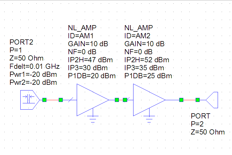
I calculated the total 0IP3 of two amplifier block.
1st block has G1(power gain)=10dB and OIP3-1(output intercept point)=30dBm.
2nd block has G2(power gain)=6db and OIP2-2=35dBm

using derivation 1/OIP3=(1/OIP3-1*G2) + (1/OIP3-2) I calculated over 0IP3.
After i simulated it in AWR 2004 and take not accurate results . And i dont understand why OIPN is depend on input power of the fundamental component in ?
for example, at Pin=-30dBm AWR show OIP3=30.605 dBm
at Pin=-10Bdm AwR show OIP3=16.7 dBm
P1db=10dbm for two amplifiers.

:?: why it occurs? What desing environment I should use to verify any calculating concerned with intermodulation distortion?

Tank advance
 

1. OIP3 should be measured well below the (at least 30 dbm or more below) the OIP3.
In your case you have measured with Pin = -10 dBm, Pout = +6 dBm, so it is
much too close to the P1dB and OIP3.
Try it with Pin= -40 dBm, and it should be approx the same as in the case of Pin=-30 dBm
2. Are you sure that P1dB and OIP3 are about 20 dB apart ? Usually it is about 10 dB.
 

thank you

Added after 11 minutes:

Thank you.
I have such amplifier. I calculated overal OIP3 about 35dbm, but AWR give me 33.57dBm. I dont't understand why result is different? Can i trust AWR or derivation of total OPI3? or maybe i'm mistaking


Added after 7 minutes:

Sorry, amplifier is invisible :)


If I read it right, in your AWR simulation, you used 10dB gain for the second stage, not 6dB. If the correct gain is used, you should see calculation and simulation in good agreement.

20dB difference between P1dB and OIP3 is normal for amplifers of high linearity .
 

Rfsurfer, thank you very much.
I have almost understood. at first, sorry for my enlish, i speak little. it presents some difficulties for me and other people. That's why i have some questions? Could you advice me?
I read the paper which attached here. And i don't understand why the intermodulation distortion are converted to voltages distortion and after added.
Assume two cascaded stages.
IM3_1 - output distortion power generated in stage 1,
IM3_2 - output distortion power generated in stage 2,
IM3 - overall distortion (watts or milliwats).
Can i add the ditstortion power due to stage 1 and stage 2 referred to output all system as
IM3=IM3_1*G2+IM3_2 (watts or milliwats) ?
where G2 - power gain of stage 2.
 

g579 could you help with last point?
 

Status
Not open for further replies.

Part and Inventory Search

Welcome to EDABoard.com

Sponsor

Back
Top