genxium
Junior Member level 3
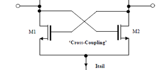
This is a figure I encountered in this article: **broken link removed**, I calculated the impedance in this way and I got -2/gm, is there anyone can give me a hand? I think maybe I misunderstood something,some concepts about "impedance for port".
My calculation
For ideal NMOS FET, Ig=0, hence denote the voltage difference applied on d1,d2 is \[V\], and the corresponding current is \[I\], then
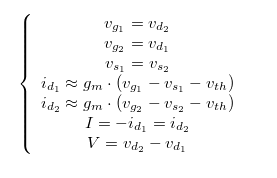
Hence the equivalent impedance for this component combination is Z=V/I=-2/gm.
PS: Seems Latex doesn't work well in this forum, could someone tell me why I got a compiled failed even for a subscript inside the \[ and \] tags?
My calculation
For ideal NMOS FET, Ig=0, hence denote the voltage difference applied on d1,d2 is \[V\], and the corresponding current is \[I\], then
Hence the equivalent impedance for this component combination is Z=V/I=-2/gm.
PS: Seems Latex doesn't work well in this forum, could someone tell me why I got a compiled failed even for a subscript inside the \[ and \] tags?