Continue to Site

Welcome to EDAboard.com

Welcome to our site! EDAboard.com is an international Electronics Discussion Forum focused on EDA software, circuits, schematics, books, theory, papers, asic, pld, 8051, DSP, Network, RF, Analog Design, PCB, Service Manuals... and a whole lot more! To participate you need to register. Registration is free. Click here to register now.

Why do we response which rises quickly to the peak value and then settles down slowly

Status
Not open for further replies.

iVenky

Advanced Member level 2
Joined
Jul 11, 2011
Messages
584
Helped
37
Reputation
76
Reaction score
35
Trophy points
1,318
Location
College Station, Texas
Activity points
6,124


I have attached a problem that is found in most of the channels- intersymbol interference. A square pulse is applied and the response is seen to be as shown in the figure. It is seen that the response reaches the peak value fast and then falls down to zero slowly. What's the main reason behind this? Don't tell me that it is because of the RC model. The peak value appears after Ts. This also results in the number of precursor taps to be lesser than the number of post cursor taps in the equalizer.

Thanks a lot
 
Last edited:
There is energy in the edges of the narrow pulse, which
is why the voltage overshoots the flat-top. And the pulse
width does not exceed the bandwidth, so the negative
edge is pulling back most of its predecessor's energy (but
not all). Now you are left with no drive, only load bleed
to settle out the system and that's slow.

You might gain insight by looking at signals that don't
rub up against the filter bandwidth, and then pushing
into the limit case. Likewise from looking at impulse
response and then widening. If you're a "gut feel" sort.
 

Hi dick_freebird. Thanks for the answer. What do you mean by "pulse width does not exceed the bandwidth"? How can you compare time domain with the frequency domain. Do you mean the pulse frequency is lesser compared with the bandwidth. Also what do you mean by "rub up against the filter bandwidth"? I would be really happy if you could explain the same thing to me much more clearly.
Thanks :)

- - - Updated - - -

Is it like squeezing a toothpaste out. I mean initially it is easy and it comes out very fast and later on it becomes difficult and comes out slowly ?
 

Find attached my explanation.

answer.jpg
 

Hey Milad. Thanks for the answer but as I have told before this is the response to the RC circuit. I see that you have modeled the line as a RC. In that response you don't have the wave reaching peak quickly. ( I mean both rising and falling have the same time constant). What I have shown you is different. This is the key reason for the no of precursors to be lesser than the no of post cursors.
 

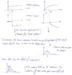
It is not about RC. Every system that has a bandwidth limitation distorts the pulse shape: It can be RC, fiber optics or anything-else. The bandwidth limitation can be due to multi-path fading. See the attachments.

a2.png

a1.png

- - - Updated - - -

This means that the order of the channel is higher than one. For example, i did a simple simulation to demonstrate that.

a3.png
 

Ya I know but why is it rising very fast to the peak value and falls at a much slower rate? The same thing happens in your simulation output too. It has risen very fast to the peak value and then falls down slowly towards zero.
 

Status
Not open for further replies.

Part and Inventory Search

Welcome to EDABoard.com

Sponsor

Back
Top