Continue to Site

Welcome to EDAboard.com

Welcome to our site! EDAboard.com is an international Electronics Discussion Forum focused on EDA software, circuits, schematics, books, theory, papers, asic, pld, 8051, DSP, Network, RF, Analog Design, PCB, Service Manuals... and a whole lot more! To participate you need to register. Registration is free. Click here to register now.

Why do the LED's not flash?

Status
Not open for further replies.

rotary

Junior Member level 3
Joined
Oct 10, 2011
Messages
25
Helped
1
Reputation
2
Reaction score
1
Trophy points
1,283
Activity points
1,474
Here is the circuit i've made, it's a 2 LED flasher circuit. I have followed this schematic as best as I can but the LED's just light up but don't flash.

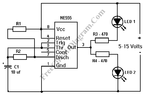
Here's the schematic -

**broken link removed**

here's a photo of the circuit-

2011-10-10 13-40-01.750.jpg


And here's a drawing so of the circuit so you can see where the connections are-


2011-10-10 14-06-52.265.jpg

2011-10-10 14-19-15.140.jpg

Can someone please tell me what i need to change on the circuit to make the LED's flash?
The two resistors on the left of the circuit are 470 ohm and there is a 100k resistor and a 10k variable resistor on the right of the circuit. All the variable resistor does when you turn up the resistance to 10k is dim the LED at the top of the circuit a bit and make the LED brighter when the resistance is turned down to 0 ohms.
 

Attachments

  • 2 led-flasher-555.gif
    2 led-flasher-555.gif
    8.4 KB · Views: 86

You mean both LEDs are illuminating together?
The possible reasons are:

1> Your astable is running at higher frequency and you are viewing both at a time (persistence of vision)
But since you are using 10uF, 100k, 10k , it should give a frequency of 'about' 1 Hz aprox. and this must be visible as blinking LEDs!!:roll:
Check all the resistors and capacitor values ones again and verify it is the same as above(if those are lower values, it may show both LEDs glowing at a time due to the increased frequency)

[Also, it is better to connect the 10k resistor from vcc to pin 7 and the 100k from pin 7 to pin 6 to make the duty cycle 'almost' near to 50%... But be careful not to make the variable resistor 0 ... Also, I think there is no need of 10k variable there, just connect a fixed 10k and if needed, use a 100k variable to increase the blinking speed)..]


Still not working? then the next possibility what I feel is:
2> Your 555 may be bad:cry: and the output is open (high o/p resistance)..
2> Or there may be some continuity problem in the breadboard...Check there is a connection even if you inserted the wires in the right position...

Also, I have a doubt that it may happen if the supply voltage is higher, but not sure about that... (this depends on the 555 output impedance )

I think you can confirm it by testing it after removing one LED...
 
Last edited:

Double check your wiring and polarity. Add a 10 nF capacitor from pin 5 to ground.
 

I checked my wiring and polarity ( even though I think i must have wired it up wrong) and added a 10nF capacitor from 5 to ground as you said but that made no difference. Any idea of where I might have gone wrong on the wiring and placement of the components?
 

Yeah, 1 to ground worked. Thanks, I overlooked that.
 

Status
Not open for further replies.

Part and Inventory Search

Welcome to EDABoard.com

Sponsor

Back
Top