Continue to Site

Welcome to EDAboard.com

Welcome to our site! EDAboard.com is an international Electronics Discussion Forum focused on EDA software, circuits, schematics, books, theory, papers, asic, pld, 8051, DSP, Network, RF, Analog Design, PCB, Service Manuals... and a whole lot more! To participate you need to register. Registration is free. Click here to register now.

Why didn't I get the voltage drop expected on diode rectifier?

Status
Not open for further replies.

red913

Newbie level 5
Joined
Mar 28, 2013
Messages
9
Helped
0
Reputation
0
Reaction score
0
Trophy points
1,281
Activity points
1,370
I got some 1N4001 diodes and putting 3 in series gave me a voltage drop of about only .4V. I don't understand why I didn't get more? I need about 3V drop. I'm not quite sure what to look for on the data sheet either. If someone could direct me in what I did wrong or direct me to the proper diode(I think the one I ordered may be incorrect) I would be very grateful.
 

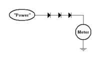
Power goes to the first diode diode and then I put the meter on the end of the third diode connected in series and the other end of the meter to ground. Also the motor itself runs a lot harder. I don't have anything to measure the current right now. Of course now that I think about it the motor running harder could be the new wall plug in power supply I have. It runs at 3A vs my previous method of power which was just 4 AA batteries.
 

Power goes to the first diode diode and then I put the meter on the end of the third diode connected in series and the other end of the meter to ground.
What you're describing sounds like this:


But that doesn't make any sense. Can you explain a bit more? What's the motor connected to? Are the diodes supposed to be in series with the motor, or what?
 

I think you are measuring the voltage with open circuit.....
OPEN.png

The circuit will work as you expected when it has a closed path.....
CLOSED.png
 

Status
Not open for further replies.

Part and Inventory Search

Welcome to EDABoard.com

Sponsor

Back
Top