Continue to Site

Welcome to EDAboard.com

Welcome to our site! EDAboard.com is an international Electronics Discussion Forum focused on EDA software, circuits, schematics, books, theory, papers, asic, pld, 8051, DSP, Network, RF, Analog Design, PCB, Service Manuals... and a whole lot more! To participate you need to register. Registration is free. Click here to register now.

Why Circuit is not outputting max voltage?

Status
Not open for further replies.

roineust

Member level 3
Member level 3
Joined
Jul 2, 2013
Messages
58
Helped
0
Reputation
0
Reaction score
0
Trophy points
1,286
Visit site
Activity points
1,903
Hello!

I am using the following circuit, with a LiPo 3S 11.1V (which charged, outputs 12.5V), with a split from the bat, one side to a regulator, that converts to 5V towards the Arduino and rest of chip legs, that need 5V and the other split side, stays 12.5V, for the motor that is switched on/off, by the chip via the Arduino, here is the schematics (in case you can't see the link, a picture is attached) :

**broken link removed**

I have 2 questions, regarding this circuit:

1. Why when bat is fully charged (12.5V), still, the motor gets only about 10.5V? Is it the grade of the pot i am using? should i use a higher quality pot? What would happen, if i used instead of that 10k pot a 5k pot? How can i get the full 12.5V?

2. If i want to have this circuit without a pot, just switch the max 12.5V on/off, without changing the voltage, what should i change in the circuit?

Thanks a lot!
 

Attachments

  • Switch_circuit.JPG
    Switch_circuit.JPG
    126.2 KB · Views: 124
Last edited:

Re: Why Circuit not outputting max voltage?

Audioguru, i also attached a picture of the schematic.

Meanwhile, more questions popped up:

Attached is a circuit i found with a mosfet.

Will this circuit do the exact same thing, as the circuit with the chip and pot, just without the pot function (which i don't need anyway), and give me switching for max voltage? If so it is good for me, but a few more questions:

1. Will it work also with 12.5V battery and motor or just with up to 9V bat and motor? The mosfet type is: irf540n, mofet weight: 3 grams.

2. Can i find a mosfet that will do the same thing, but weight less? Do you know that mosfet model number? If there exists such a mosfet, should the circuitry be just the same, just replace the mosfet model?

3. i intend to switch it once every 2-10 seconds.

Thanks.
 

Attachments

  • wHFchDt1.JPG
    wHFchDt1.JPG
    120.7 KB · Views: 105
Last edited:

Re: Why Circuit not outputting max voltage?

You did not post the schematics. Instead you posted photos of a layout of parts on a breadboard.
There is an Arduino but I do not know if it uses PWM for motor speed control and I do not know its frequency.

I do not know who makes the motor and I do not know its maximum current.

The first breadboard layout shows an L293D driver. Its datasheet shows that its maximum output voltage loss is 1.8V for each output at a current of 1A. So your voltage loss to the motor can be 3.6V or more.

The second breadboard layout shows an IRF540 Mosfet. It is driven with only 5V from the Arduino but its datasheet shows that it needs 10V to fully turn on and each one is different so we do not know its voltage loss in your circuit. The Mosfet should be an IRL540 that turns on completely with an input of 5V from the Arduino. Its voltage loss will be extremely low.

The intermittent contacts on the breadboard will have a high voltage loss. Use soldered connections on a pcb or soldered on a stripboard instead.

I have many products with tiny Mosfets that produce a very low voltage loss when driven from a small voltage but I do not know their part numbers.
 
Re: Why Circuit not outputting max voltage?

Thanks for replying.

I have been DIY electronics, for exactly a year. So excuse me for not knowing the difference between a layout and a schematics.

Soon i will return with more focused questions...

- - - Updated - - -

Current draw of the motor is around 3A.

What is the best way for a beginner, that can't really understand the specs of components in huge professional sites, such as DigiKey, to find a mosfet, that can be connected according to the above LAYOUT (hope i got it right this time...), that can handle around 3A and is weight wise, less as possible, in comparison to the the IRF540, which weighs 3 grams?

Thanks!
 

Re: Why Circuit not outputting max voltage?

A transistor gives fewer uncertainties about biasing, etc. You could use an NPN in the same position as your mosfet.

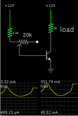
A potentiometer sets bias current. A safety resistor is recommended.

Your motor regulates itself to draw a certain amount of amperes. Since you want to give it access to full voltage, then your goal is to bias the transistor, so it admits more than ample current to power the motor. Possibly 3X as much, to take care of start-up surge.

9518756800_1391736810.png
 
Re: Why Circuit not outputting max voltage?

Hey Brad!

Please try to explain a simpler explanation!

I am having a problem understanding the terms and picture you are using, they are too high level for me (i mean the scope slopes at the bottom)!

What model number of NPN?
Will i need to use only these 3 resistors? 20k, 3 and 3.3k and the rest of the layout, just as the one i attached with the mosfet ? How can i make this biasing happen?

Thanks!
 

Re: Why Circuit not outputting max voltage?

What is an NPN? What type of NPN?

Google "NPN transistor". The transistor type all depends on the voltage, current, [power disp.] and gain that is required. BTW there should be a reverse-biased diode across the load[motor].

Motors typically have a high inrush[starting] current, so the transistor must be able to handle that.

A common transistor that should work here is the TIP31.


- - - Updated - - -

Will i need to use only these 3 resistors? 20k, 3 and 3.3k and the rest of the layout,

I think you made a typo - it shows a 30 ohm load - it is the load[motor in your case] - not an actual resistor.

- - - Updated - - -

How can i make this biasing happen?

The circuit Brad showed sets the bias.
 
Re: Why Circuit not outputting max voltage?

A transistor is big and heavy. It needs a big and heavy heatsink because it has a high voltage loss (1.2V max) at 3A. A TIP31 transistor will probably burn out (its maximum allowed current is 3A) when the motor draws more than 3A when it starts and when it stalls.

For 3A in the transistor then the potentiometer will also burn out when it has 375mA in it. Where will the 375mA base current come from? From another transistor with even more voltage loss?
 
Re: Why Circuit not outputting max voltage?

. A TIP31 transistor will probably burn out (its maximum allowed current is 3A) when the motor draws more than 3A when it starts and when it stalls.

in the OP he shows 4 AAA batteries in series as the supply voltage - can a AAA battery deliver more than 3A ?!
 
Re: Why Circuit not outputting max voltage?

Hey Audioguru!

I am intending to use a LiPo 1A 25C 3S 11.1 volts (charged 12.5 volts).

The Arduino is for switching the motor on and off from a bluetooth.

The continuous current of the motor is around 3 Amps and the stall current is somewhere between 40-60 Amps, but i don't believe it will get any close to that, since it will run a liquid pump and either pump the liquid or be shut off.

But, maybe i also don't understand well enough the term 'stall'.
 
Last edited:

Re: Why Circuit not outputting max voltage?

See? By posting the WRONG photo then some people think your powerful 12.5V Li-Po battery is only a few AAA cells. A 1Ah Li-Po battery can easily supply 20A for a few minutes. But it is rated to supply 1A for 1 hour.

Your motor starts from a stall. If the liquid freezes or has a big wooden log in it then it will stall and draw a high current.

The Arduino can be replaced by one transistor.
 
Re: Why Circuit not outputting max voltage?

Hey Brad!

Please try to explain a simpler explanation!

I am having a problem understanding the terms and picture you are using, they are too high level for me (i mean the scope slopes at the bottom)!

What model number of NPN?
Will i need to use only these 3 resistors? 20k, 3 and 3.3k and the rest of the layout, just as the one i attached with the mosfet ? How can i make this biasing happen?

Thanks!

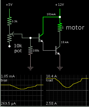
Since the motor draws 3A, I revised my schematic.

You'll need a power transistor to control the motor.

If you use a 5V device to do this, it may not provide sufficient bias current. Two low-gain transistors (in darlington array) will take the place of one high-gain transistor.

My schematic uses values which work okay for a 5V control signal coming in (at left).

The scope traces show a range of bias settings, and the resulting current through the load. Each transistor is 100 gain. Notice the proportions: 1 mA maximum bias, and 10 A maximum load.

I represented your motor as a 1 ohm resistor, since it might need 9 or 10 A surge current on power-up.

A suitable power transistor is the 2N3055, inexpensive and widely available. It will probably need heat sinking.

The above is not necessarily superior to using a mosfet, but it's an alternate method for driving your motor.

- - - Updated - - -

5764233700_1391760287.png
 
Re: Why Circuit not outputting max voltage?

Brad,
Should the lower side of the 10K pot, also connect to ground? I ask it since, in contrast to the 100k and second transistor, it doesn't have the ground sign, but only a white dot at the lower end.
 

Re: Why Circuit not outputting max voltage?

Since the motor draws 3A, I revised my schematic.
Two low-gain transistors (in darlington array) will take the place of one high-gain transistor.
You do not show a darlington array. Instead the first transistor will probably burn out because it has high voltage and high current. The collectors are connected together in a darlington array.

Each transistor is 100 gain. A suitable power transistor is the 2N3055.
NO WAY!
The datasheet for a 2N3055 transistor shows that its maximum saturation voltage is 3V when its collector current is 10A and its base current is 3.3A! Then the gain is only 3.
 

Re: Why Circuit not outputting max voltage?

Brad,
Should the lower side of the 10K pot, also connect to ground? I ask it since, in contrast to the 100k and second transistor, it doesn't have the ground sign, but only a white dot at the lower end.

You can connect the 100k resistor to the pot's lower terminal.

(The white dot on one end is not an error in the simulator. It is okay to use the pot as a variable resistor.)

Adding a resistor to ground is a good idea. If the control device is ever disconnected while the power supply is On, you do not want to leave the transistor base floating and exposed to stray signals (including static charge and ambient mains hum). The motor could turn on when you don't want it to.

- - - Updated - - -

You do not show a darlington array. Instead the first transistor will probably burn out because it has high voltage and high current. The collectors are connected together in a darlington array.

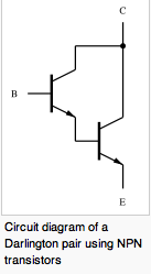
I thought I arranged two transistors in darlington fashion, according to this diagram (found at wikipedia):

7513319100_1391792014.png


I agree the first transistor will be called on to dissipate a lot of wasted heat. 1 watt, maybe 2. It will burn up if it is not a medium-power package at least.

NO WAY!
The datasheet for a 2N3055 transistor shows that its maximum saturation voltage is 3V when its collector current is 10A and its base current is 3.3A! Then the gain is only 3.

I did not expect to drive the power transistor base with 3.3A. More like a couple hundred mA.

True, the 2N3055's gain is way less than 100. My schematic would need further revision. Nevertheless it shows how to drive a 10A load, when the control signal is uncertain, and perhaps limited to a few mA.
 
Status
Not open for further replies.

Part and Inventory Search

Welcome to EDABoard.com

Sponsor

Back
Top