Continue to Site

Welcome to EDAboard.com

Welcome to our site! EDAboard.com is an international Electronics Discussion Forum focused on EDA software, circuits, schematics, books, theory, papers, asic, pld, 8051, DSP, Network, RF, Analog Design, PCB, Service Manuals... and a whole lot more! To participate you need to register. Registration is free. Click here to register now.

Why ballast kick voltage do not get bypassed through starter?

Status
Not open for further replies.

ahsan_i_h

Full Member level 5
Joined
May 18, 2012
Messages
290
Helped
80
Reputation
160
Reaction score
77
Trophy points
1,308
Location
Bangladesh
Activity points
3,245
Hello everybody
For a 220v conventional ballast(electrical), starter, fluroscent tube system, during starting, Why ballast kick voltage(appx 1000v) do not get bypassed through starter? We know that starter threshold voltage is lower than 220v.
 

Dear ahsan
Hi
I think you're talking about old light bulbs ( white light ) with an inductor and an starter , right ?
Best Wishes
Goldsmith
 

Yes. The ballast is the inductor. The tube is the four feet white fluroscent lamp and the starter is something like bimetal switch in vacuam glass container.
 

as you know the starter is in parallel with your bulb and the inductor is in series to provide a fast transient response ( hit )
this hit is needed to excite the gas inside the bulb . after that , that gas will be a conductor ( approx ) . thus the current will go through it . and the duty of starter is : creating a fast hit , thus the inductor can create those instantaneous voltages .
After some seconds the starter will be out of circuit , because : at start time , the current will go through the start , and the gas inside the starter will going to be warm , and thus the bimetal will be active and will short circuit the gas inside the starter , thus it will go out of the circuit and then current can go through the series inductor and the gas inside the bulb .
I hope i correctly understood that what is your problem .
Best Wishes
Goldsmith
 

When the starter makes a hit, then the generated instantaneous voltage from the inductor easily can ionize the starter gas instead the lamp vapour. We see that at low voltage (less than 220v) the starter gas glows. If it ionize the starter gas, then all the high voltage spike should get bypassed through the starter and there is no reason that the lamp will get the high voltage for ionization.
 

Do you know what is the cause of that high voltage ? the start and inductor !!!! and when the gas inside the lamp , ionize , there won't be any path for start , hence you can open it after the time that your lamp is turned on !
The inductor can't increase the voltage without an impulse . the starter will be the cause of that impulse .
Best Luck
Goldsmith
 

Thank you goldsmith for your reply,
Yes starter is the cause of the impulse. But that impulse will hit both the lamp and the starter(because they are parallel connected). Insted of breakdown the starter, how it breakdown the lamp? (breakdown the starter is easy because it is partially vacuam and the elecrtodes are close to each other). We know below 220v the starter gas breakdown(we can see that starter is glowing before it make the impulse)
 

I'm a bit confused , if that high voltage go through the start what will happen ? nothing special . why it is important ?
 

Thankyou for your reply goldsmith.
If that high voltage go through the starter then the lamp will not get sufficient voltage(like 1000v),which is neccerary to ignite it. You know when high voltage leaks to ground or somewhere we do not get high voltage.
 

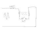
See below , please , i draw electrical circuit of this lamp , ( i'm a bit lazy to draw , them , hence , i draw it in paint ) .
untitled.JPG
I think thus your problem will solve .
 

When the start is off ( it will be on and then off and on and then off , fore some little times )
so when the start is off , the high voltage will be across the tube .
 

The diagram doesn't fully explain the behaviour, I think. The glow discharge lamp is in parallel to the bimetal switch. The answer is in the I-V characteristic of the glow discharge lamp. Apparently it's intrinsically current limited at several 10 mA.
 

Thankyou FvM for your reply.
I know that glow discharge lamps(example neon lamp) are constant voltage device, thats why we put a series resistance with neon lamp when we connect it to mains 220v. It might be a constant current device at higher current(several 10mA), but I just seen neon lamp's I-V from www.nutsvolts.com/uploads/magazine.../NeonLamp-Information.pdf, that it is a constant voltage(even lower voltage) device at higher current when it get destroyed.

---------- Post added at 17:51 ---------- Previous post was at 17:43 ----------

Sorry for the incomplete link. The actual link is https://www.nutsvolts.com/uploads/magazine_downloads/NeonLamp-Information.pdf
 

New Bitmap Image (2).PNG
https://home.howstuffworks.com/question337.htm
Simple ac phase current passes thru ballast coil next thru tube filament thru neon gas in the starter (glows)once again thru other tube filament and to neut.
the current heats up the filament in the tube resulting a cloud of electrons.
when the ballast produce high voltage the current passes from filament to filament lighting the tube and the gas in tube has lower voltage holdup than the neon so neon not needed any more.
 

Thank you dselec for your reply.
You know we do not put a basic neon lamp(only a glass capsule with two electrode) directly to the mains 220v. Why? because it is act like two back to back zener(actualy it is like diac). We never connect zener or diac directly to supply voltage, but we put a series resistor before do that. Thats why we put a series resistor with neon lamp before we connect it to mains.
Now when such a neon lamp(the starter at off state) which act as like 160v zeners,diacs ets connected parallel to the four feet lamp, how high voltage will rise? constant voltage devices like neon,zeners,diacs will not let the voltage to rise more than 160v.
I thought the neon lamp will become a constant current device(which will let voltage to rise but not current) when its current increses to several 10mA. But the I-V characteristics from https://www.nutsvolts.com/uploads/magazine_downloads/NeonLamp-Information.pdf clearly shows that a neon lamp is still taking more current upto its destruction but does not let its voltage to rise.
 

How Fluorescent Lamps Work 8 Pages
https://home.howstuffworks.com/fluorescent-lamp4.htm

When the lamp first turns on, the path of least resistance is through the bypass circuit, and across the starter switch. In this circuit, the current passes through the electrodes on both ends of the tube. These electrodes are simple filaments, like you would find in an incandescent light bulb. When the current runs through the bypass circuit, electricity heats up the filaments. This boils off electrons from the metal surface, sending them into the gas tube, ionizing the gas.

At the same time, the electrical current sets off an interesting sequence of events in the starter switch. The conventional starter switch is a small discharge bulb, containing neon or some other gas. The bulb has two electrodes positioned right next to each other. When electricity is initially passed through the bypass circuit, an electrical arc (essentially, a flow of charged particles) jumps between these electrodes to make a connection. This arc lights the bulb in the same way a larger arc lights a fluorescent bulb.

One of the electrodes is a bimetallic strip that bends when it is heated. The small amount of heat from the lit bulb bends the bimetallic strip so it makes contact with the other electrode. With the two electrodes touching each other, the current doesn't need to jump as an arc anymore. Consequently, there are no charged particles flowing through the gas, and the light goes out. Without the heat from the light, the bimetallic strip cools, bending away from the other electrode. This opens the circuit.

**broken link removed**

By the time this happens, the filaments have already ionized the gas in the fluorescent tube, creating an electrically conductive medium. The tube just needs a voltage kick across the electrodes to establish an electrical arc. This kick is provided by the lamp's ballast, a special sort of transformer wired into the circuit.

When the current flows through the bypass circuit, it establishes a magnetic field in part of the ballast. This magnetic field is maintained by the flowing current. When the starter switch is opened, the current is briefly cut off from the ballast. The magnetic field collapses, which creates a sudden jump in current -- the ballast releases its stored energy.

**broken link removed**

This surge in current helps build the initial voltage needed to establish the electrical arc through the gas. Instead of flowing through the bypass circuit and jumping across the gap in the starter switch, the electrical current flows through the tube. The free electrons collide with the atoms, knocking loose other electrons, which creates ions. The result is a plasma, a gas composed largely of ions and free electrons, all moving freely. This creates a path for an electrical current.

**broken link removed**
 
Last edited:
Dear tpetar
Hi
The pictures that you attached are very good , thank you for them . i compared them with my attachment and i saw that what an awful picture is that i have attached !! :-D
Best Regards
Goldsmith
 

Goldsmith my friend your picture is better that picture comes from your hand, I found this nice pictures on Internet.

All pictures are good if viewer catch the point. This is invalid in case of Picassos pictures. ;-)
 

I must admit, that I didn't think before about your specific question. The "current limited I-V characteristic point" is just a conclusion. I would need to measure a real device to verify it.

Apparently the question is too sophisticated to be considered in popular explanations of fluorescent lamp operation like "how stuff works" or wikipedia. I also agree that I know negative impedance of glow discharge tubes as the standard model.

I reviewed my vacuum electronics literature and found an "abnormal glow discharge" region mentioned. Apparently, the current can be controlled by varying the gas pressure. It's also mentioned in wikipedia: https://en.wikipedia.org/wiki/Electric_discharge_in_gases
 

Status
Not open for further replies.

Part and Inventory Search

Welcome to EDABoard.com

Sponsor

Back
Top