Continue to Site

Welcome to EDAboard.com

Welcome to our site! EDAboard.com is an international Electronics Discussion Forum focused on EDA software, circuits, schematics, books, theory, papers, asic, pld, 8051, DSP, Network, RF, Analog Design, PCB, Service Manuals... and a whole lot more! To participate you need to register. Registration is free. Click here to register now.

[SOLVED] Which transformer to use?

Status
Not open for further replies.

ADGAN

Full Member level 5
Joined
Oct 9, 2013
Messages
295
Helped
4
Reputation
8
Reaction score
4
Trophy points
18
Activity points
1,837
Hi! In my application I used a 12V 300mA transformer, but when I connect a GSM modem it did not work after initialization. Many suggested that I should use a 12V 1A transformer. I want to know whether it will affect the rest of the circuit? (Whether other circuit components will get burnt)
 

What did you use exactly and what are the supply requirements for your GSM modem? Nowadays a "transformer" can be anyting between a steel laminate E type transformer, but also a small regulated switching power supply.
 

The GSM modem needs 500mA. I purchased a 1A power transformer. I don't know the type.
 

What about voltage?

Assuming "1A power transformer" is just a steel laminate mains transformer, you can't use it. The transformer outputs AC voltage/current and your modem needs DC (unless otherwise noted).
 

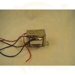
Transformer is 12V. I'm using a bridge rectifier to convert it to DC and LM7812 to regulate it to 12V. This is the type of transformer I'm using:

dsc09027_1_1_.jpg
 
Last edited:

It looks like a center tapped transformer. check the voltages with an AC voltrmeter, if you have 24 V between some of the black wires, it is a center tapped transformer. If so use a two diode rectifier as shown here: https://en.wikipedia.org/wiki/Rectifier#Full-wave_rectification

Scroll to the center-tap image with two diodes.

If you need 500mA DC supply, a 500mA transformer is too small, you should have > 900mA

To fill the dips that go to zero, use a 3300uF (or larger) capacitor after the rectifier (observe polarity). Measure the output with a voltmeter with a 500 mA resistive load (that is large resistor of 28 Ohms). Do this for short term only, as you are overloading the transformer.

When using 3300uF capacitor, the ripple will be 1Vpp with 500mA load. A LM7812 needs about 14 V input voltage (at 1A output). So the reading on your voltmeter should be around at 14.5V. If you have significantly less voltage, you can't use the LM7812 and in that case you need to find a "low drop out" regulator (or complete other solution).

When you have about 14.5V, you can use the LM7812. Make sure to read the application info to avoid parasitic oscillation (and EMC issues with the pulsed RF signal from the GSM modem).

Your modem will very likely use max 500mA peak current during the on cycle of the RF PA only (due to the time slots in GSM). The average current during transmit will be very likely less. So when the rectified voltage at 500 mA is (for example) 13.5V, the regulator may do the job as the average load of say 100mA will result in more rectified output voltage. The current peaks are drawn from the 2200uF capacitor.

- - - Updated - - -

If you use your new 1A transformer, this should be fine. I would use somewhat larger rectifier then 1N400X as this results in less voltage drop across the diode (and less generated heat in the rectifiers).

2200uF instead of 3300uF is fine, as the output voltage with 500mA load is higher, so you can accept more ripple. If you have an oscilloscope, you can check the rectified wave form when drawing (for example) 500mA.
 
Last edited:
  • Like
Reactions: ADGAN

    ADGAN

    Points: 2
    Helpful Answer Positive Rating
Thank you very much for the reply. Does a 1000uF capacitor is sufficient for this purpose?
 

If you have an oscilloscope you could measure the rectified output voltage with capacitor and some load. The "problem" with 1000 uF is a more then twice increase of ripple voltage (About 3.8 Vpp at 500mA ). Just do some measurement as the average load may be well below 500 mA. When the dip is too large, add another one!

Note that the no-load rectified voltage (with capacitor) can be around 20V, so do not use a 16V electrolytic capacitor (go for 25V).
 
  • Like
Reactions: ADGAN

    ADGAN

    Points: 2
    Helpful Answer Positive Rating
Status
Not open for further replies.

Similar threads

Part and Inventory Search

Welcome to EDABoard.com

Sponsor

Back
Top