awan
Advanced Member level 4
- Joined
- Jun 11, 2004
- Messages
- 106
- Helped
- 0
- Reputation
- 0
- Reaction score
- 0
- Trophy points
- 1,296
- Location
- Los Angeles
- Activity points
- 815
op amp gain non inverting sallen key
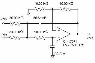
I need to design 250Hz sallen key filter and looking for good opamp. I only have single supply at 3volts. I used AD824 and my design works for +3volts and -3volts supply. But it doesnt work for +3volts and 0 supply although the data sheet says that its a single supply opamp.
I cant push the input to 1.5votls as I need to use several stages and also have a gain from the filter.
Thanks