Continue to Site

Welcome to EDAboard.com

Welcome to our site! EDAboard.com is an international Electronics Discussion Forum focused on EDA software, circuits, schematics, books, theory, papers, asic, pld, 8051, DSP, Network, RF, Analog Design, PCB, Service Manuals... and a whole lot more! To participate you need to register. Registration is free. Click here to register now.

Which device can I use ?

Status
Not open for further replies.

milan.rajik

Banned
Joined
Apr 1, 2013
Messages
2,524
Helped
540
Reputation
1,078
Reaction score
524
Trophy points
1,393
Activity points
0
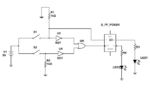
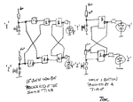
I have to control a bi color LED from two signals lines. The CC or CA pin of led will be connected to power GND or +ve rail through a 330E resistor. When one button is pressed (signal goes low) the green led has to turn ON and when another button goes low the red LED has to turn ON. Only one button can be low at a time. Both high or both low is invalid. Once a button is pressed and signal goes low then that led color has to remain ON till another signal goes low. Which logic device can I use for this ?
 
Last edited:

Use NOT Gate. The input signal must be directly applied to one terminal and to the input of NOT gate. The output of NOT gate must be connected to another leg of LED. This IC is 74HC04
 
I have done that but it doesn't work as I need because when signal goes low then one led turns ON and another turns OFF but what I want is when one signal goes low red led has to turn ON and green led has to turn OFF and the LED state has to remain unchanged until the second signal goes low. When 2nd signal goes low red led has to turn OFF and green turn ON and then remain in that state until signal one goes low again. Once a state of led is toggled due to a signal then it should not change on repeated triggering of the same signal.
 

I tried that but didn't work. Here LEDs has to change state only when signal goes low.

It worked I put two NOT gates one for each input of SR FF.
 

    V

    Points: 2
    Helpful Answer Positive Rating
74LS137 addressable latch might work.

See attachment.

Allen
 

Attachments

  • addressable latch.GIF
    addressable latch.GIF
    147.8 KB · Views: 105
Use a combination of S-R Flipflop or J-k Flip Flop with NOT gate to achieve your specs.
 

OK here is your problem according to me:
1. There are two inputs, input A and input B.
2. Input A goes low and returns to high. LED 1 must light as soon as A goes low, and continue even if A becomes high.
3. Input B goes low and returns to high. LED 2 must light as soon as B goes low, and continue even if B becomes high.
4. As soon as a signal goes low, the 'other LED' not associated with the signal must turn-off.
I think you missed mentioning that even if the input goes high the LED must not turn off. Am I right?

Before seeking the solution, one more question needs to be answered....
Is there a possibility of pressing a button more than one time continuously without pressing the other button between consecutive presses? (In other words, If LED 1 is ON then can switch A be pressed again to turn it on)
 
4. As soon as a signal goes low, the 'other LED' not associated with the signal must turn-off.
I think you missed mentioning that even if the input goes high the LED must not turn off. Am I right?

Is there a possibility of pressing a button more than one time continuously without pressing the other button between consecutive presses? (In other words, If LED 1 is ON then can switch A be pressed again to turn it on)


Yes, I mentioned that button A or B can go low repeatedly but once a LED state changes then it should not change until the other signal goes Low. I need 3 such circuits for a total of 6 buttons. 2 buttons for one Bi-Color LED (Common Cathode).
 

The circuit you want is known as RS latch and is usually implemented by two cross-coupled NAND2 gates, e.g. 7400.
 
When you say both signals high or both signals low is an invalid condition.

Does that mean you always press a button? If no button is pressed, both will be in the same condition, and this is invalid?
 

You need a microcontroller to achieve the result.
 

Ok here's the circuit! I have simulated it and it works fine. See the attachment.
Note that the 'hold time' of the flip flop must be less than the propagation delay of the OR gate.

- - - Updated - - -

This circuit also takes care of both S1 and S2 going high/low simultaneously. In such cases, the output doesn't change.
 

Attachments

  • EDA 3.PNG
    EDA 3.PNG
    30.9 KB · Views: 91
1. "When one button is pressed (signal goes low) " You haven't abided by his first requirement. The switches must go LOW.
2. You are going to have a lot of racing problems.
3. Repeatedly pushing the button is going to keep clocking the FF.
4. The circuit does not work. You have no switch debounce.
 
colin55:
1. The circuit works and all requirements are satisfied! The signal indeed goes low, there are inverters in series with switches.
2. Racing with what!
3. Repeated triggering of clock is required by design!

I see what you are trying to point out. But that can be solved simply by associating S2 with LED1 and S1 with LED2.
Or otherwise connect the D-pin of the flip-flop with the output inverter-1 instead of the input (as connected now)
(see simulations attached)Capture14.PNG
 
Last edited:

I said the signal lines will be high all the time and goes low only when button pressed.
 

Guys c'mon! Before arguing any further, atleast verify what that circuit posted above does. The simulation above shows clearly that the LEDs do not change state when the signal goes high.
(Lower graph is the input and the upper is the output to the LEDs. Green = LED1, Red = LED2)

What makes anyone feel that the above circuit is not working according to the requirement?
 

I said the signal lines will be high all the time and goes low only when button pressed.


OK, the next question is then. Will the buttons be pressed one at a time, or could it happen that both are pressed at the same time?

- - - Updated - - -

Here is a proposal for your two solutions.
 

Attachments

  • flipflop.png
    flipflop.png
    521.9 KB · Views: 90
Status
Not open for further replies.

Part and Inventory Search

Welcome to EDABoard.com

Sponsor

Back
Top