Continue to Site

Welcome to EDAboard.com

Welcome to our site! EDAboard.com is an international Electronics Discussion Forum focused on EDA software, circuits, schematics, books, theory, papers, asic, pld, 8051, DSP, Network, RF, Analog Design, PCB, Service Manuals... and a whole lot more! To participate you need to register. Registration is free. Click here to register now.

[SOLVED] Where to put CAN bus Termination Resistor

Status
Not open for further replies.

dhruv_electro

Advanced Member level 4
Joined
Dec 17, 2010
Messages
118
Helped
9
Reputation
18
Reaction score
8
Trophy points
1,298
Location
India
Activity points
2,378
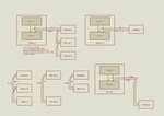
We are designing various devices for a system which communicate over the CAN bus using 250kbps. Requirement of the termination resister is as follows please see attached image:
Test.jpg

1. Termination should be on PCB not on Cable.
2. In any configuration Communication should be possible, i.e. any two device should communicate even if we plug in or plug out other devices.
3. Any plug in and plug out will occur in power off state only.
4. Please see image We can not determine where the second end of bus will be, as first end of bus is fixed at Device 1 (Function 1). But it may be possible (as seen from image) that device 1 will not present in bus.

Is there any possible solution of termination resistor?
 

we tend to have a jumper on every PCB so on the end devices we can link in the terminating resistors, e.g.
can1.jpg

do see why you cannot have a small PCB at each end of the bus with the terminating resistors though
 

You didn't mention segment and total cable length which matter a lot.

Generally, the bus should have a partyline topology and termination resistor have to be placed at both ends. One or even both might be omitted in short busses.

Depending on the used connector standard, termination resistors are often plugged to the endpoint nodes. Some CAN enabled instruments have two paralleled connectors, so you can either route to the next device or place a termination resistor.
 
Termination in Connector / Cable is not allowed and termination should be on board, which is also placed in a closed box so no jumper possible.


You didn't mention segment and total cable length which matter a lot.
Segment length is from 5 inch to 5 meter. Total Cable length is 15 meter max.

Generally, the bus should have a partyline topology
In any case of Plug in or plug out it will maintain this topology.

termination resistor have to be placed at both ends. One or even both might be omitted in short busses.

Problem is that system require to operate if any of two node is there, so we are confused that where we can solder the termination resistor.
 

Termination in Connector / Cable is not allowed and termination should be on board, which is also placed in a closed box so no jumper possible.

It's funny how designers and particularly project managers decide what's not possible in a design without planning a suitable solution from the start.

You should have proper end termination for 15 m bus length.

According to your constraints, the only option are software controlled termination resistors, e.g. using analog switches or relays, or a mechanical switch at the box outside.
 
It's funny how designers and particularly project managers decide what's not possible in a design without planning a suitable solution from the start.
I agree! sounds like some of the projects organisations have asked me to work on!
get half way thru when extra requirements start to appear!
why not a box containing a PCB with a terminating resistor at the end of the cable ?
 
It's funny how designers and particularly project managers decide what's not possible in a design without planning a suitable solution from the start.
I agree! sounds like some of the projects organisations have asked me to work on!
Ha ha.. Pain is pain anywhere in this world.:bang:
why not a box containing a PCB with a terminating resistor at the end of the cable ?
At first we suggested this. But the environment require higher standard of packing for that termination PCB, again rejected by superior, to give ease to user.
According to your constraints, the only option are software controlled termination resistors, e.g. using analog switches or relays, or a mechanical switch at the box outside.
As per we remember Microchip's CAN Bus Analyzer have similar facility to turn on Termination in Software. We need to get its schematic. Anyway thanks for the help.
 

CAN bus routes need proper planning for reliability with access points being short stubs and end points properly terminated.

Did someone forget to specify a receptacle for the endpoint resisitive terminator?

image.jpg
 

Here our approach to solve the problem seems wrong. Bus termination rules requires to be followed very tightly. We have decided to provide mechanical switches for the termination resistor in every node. We will apply the software controlled analog switches idea in later version or as per SunnySkyguy suggested special termination endpoint.

We are thankful to everyone for replying and sorry that we have wasted your time. May this thread be guide for future developers.
 

Status
Not open for further replies.

Similar threads

Part and Inventory Search

Welcome to EDABoard.com

Sponsor

Back
Top