Continue to Site

Welcome to EDAboard.com

Welcome to our site! EDAboard.com is an international Electronics Discussion Forum focused on EDA software, circuits, schematics, books, theory, papers, asic, pld, 8051, DSP, Network, RF, Analog Design, PCB, Service Manuals... and a whole lot more! To participate you need to register. Registration is free. Click here to register now.

What's wrong with this circuit?

Is the snubber circuit to complicated/overdesigned?

  • yes

    Votes: 0 0.0%
  • no

    Votes: 0 0.0%

  • Total voters
    0
Status
Not open for further replies.

prinsloo

Member level 5
Joined
Sep 19, 2004
Messages
93
Helped
2
Reputation
4
Reaction score
1
Trophy points
1,288
Location
Bethlehem RSA
Activity points
697
230v zero crossing detector circuit

Dear Members

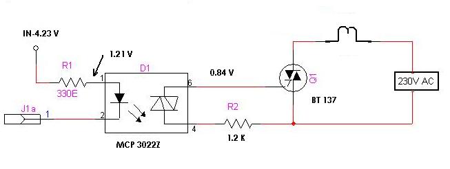
The circuit is continuously conducting 230V AC. I connected it to a uc-PIC and want to switch a series of lights on/off.


I have read something about "a zero crossing switching"
Is this done via the PIC? Is it a special program to be written?

Pls help.
Thx in advance.
 

snubber circuit wiki

Can anabody pls help me? I have seen a lot of questions about triacs but no answers.

Regards
 

this will not work because the signal applied to gate is not proper and is not with proper level.
 

Power phase control


https://en.wikipedia.org/wiki/Snubber

A snubber circuit is often used to assist this turn off. Snubber circuits are also used to prevent premature triggering.

Some kind of Averaging needed...

A capacitor stores energy in max pi/2 or T/4.

Tiristor control is possible in max pi/2.


Nice!!!

https://www.epanorama.net/documents/lights/lightdimmer.html#history


Phase Control is implemented by triggering a optotriac that switchs the snubber to the gate of triac.

This triggering circuit need a reference in time, like zero crossing detector (beginning of possible phase control), then we should control the time of triggering by comparing ramp signal (integration of pulse in zero crossing detector) with a DC variable level.

By this way we gain safety, because we don't have to control a potenciometer over mains voltage.


You have the snubber bad implemented.


Push help button
 

The snubber circuit is wrong, well you can check this circuit.
**broken link removed**

kelvin
 

    prinsloo

    Points: 2
    Helpful Answer Positive Rating
Re: Still not working

Dear Members

I tried the .jpg diagram that is available.Now the light is off-when the 5V is present it does not switch on.Is the voltage on the gate to low?

What should the voltage be? I don't understand the data sheet so well.


How do I fix it?

Thanks in advance

Regards
Johan
 

Here's one with a snubber. A zero crossing detector is a separate circuit.
**broken link removed**

And here's a typical zero crossing detector
**broken link removed**
 

    prinsloo

    Points: 2
    Helpful Answer Positive Rating
Status
Not open for further replies.

Part and Inventory Search

Welcome to EDABoard.com

Sponsor

Back
Top