tony_lth
Advanced Member level 5
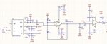
I built a simple OpAmp circuits, using AD8226ARMZ and AD8669ARUZ.
My signal is several Hz, and VREF is 1.2V.
After Diff OpAmp AD8226, I used a 10uF(C7) to isolate DC, I hope pin5 of AD8669 is just small AC signal (about several Hz), but the tested value of pin5 is about 0.6V, and the OpAmp output pin7 is about 3.3V, the up rail of OpAmp.
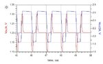
The original design is that C7 at th position of the output of U1B, but that will cause waveform distortion. See attached simualtion result.
So I changed 10uF from output of U1B to input of U1B.
1. What's wrong with it? I designed U1B with AC 750 times amplifies,but obvious DC is very high.
2. Is some ESD diode in AD8669 caused input pins of AD8669 0.6V?
3. I used ADS to simulate my OpAmp circuits, and it works well. Why in real circuit it does not work?
4. Any suggestion about the replacement with AD8669? so that input pins doesn't have 0.6V offset DC voltage?
Thanks.
My signal is several Hz, and VREF is 1.2V.
After Diff OpAmp AD8226, I used a 10uF(C7) to isolate DC, I hope pin5 of AD8669 is just small AC signal (about several Hz), but the tested value of pin5 is about 0.6V, and the OpAmp output pin7 is about 3.3V, the up rail of OpAmp.
The original design is that C7 at th position of the output of U1B, but that will cause waveform distortion. See attached simualtion result.
So I changed 10uF from output of U1B to input of U1B.
1. What's wrong with it? I designed U1B with AC 750 times amplifies,but obvious DC is very high.
2. Is some ESD diode in AD8669 caused input pins of AD8669 0.6V?
3. I used ADS to simulate my OpAmp circuits, and it works well. Why in real circuit it does not work?
4. Any suggestion about the replacement with AD8669? so that input pins doesn't have 0.6V offset DC voltage?
Thanks.