Continue to Site

Welcome to EDAboard.com

Welcome to our site! EDAboard.com is an international Electronics Discussion Forum focused on EDA software, circuits, schematics, books, theory, papers, asic, pld, 8051, DSP, Network, RF, Analog Design, PCB, Service Manuals... and a whole lot more! To participate you need to register. Registration is free. Click here to register now.

What's the easiest way to determine complex impedance of transmission line?

Status
Not open for further replies.

DeboraHarry

Full Member level 5
Joined
Dec 3, 2011
Messages
274
Helped
48
Reputation
94
Reaction score
43
Trophy points
1,308
Location
UK
Activity points
3,905
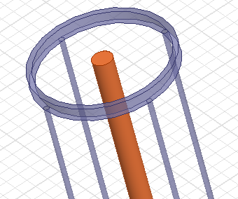
I have a transmission line, which is like coax cable, but has a deliberately poor shield, so it will radiate. I'm trying to analyse this in HFSS. What's the best way to find the impedance of the coax? Since the cable is not lossless, the impedance will be complex, and of course vary with frequency.

Deborah
 

by knowing the frequency of the signal you can easily find the complex impedance

check the manufacturer's guide for the inductance and capacitance coefficient of the cable from them calculating the complex impedance part is very easy

just try it and post

i have also not tried this so just stating a possibility

This is not a commercial cable, so there is nothing I can go on from that. It's not even round. It will act as a transmission, but also as an antenna.

IIRC, there is a relationship (which I forget), which basically says


Zin = Zload * C(alpha, beta, length)

So if a cable C has an attenuation coefficient alpha, a phase constant beta and one knows the length, one can work out what the input impedance will be. I guess if I terminate this is some load (50 Ohms would seem logical), then I have two unknowns (alpha and beta) and two knowns (the real and complex parts of the input impedance). I'm guessing I can then find alpha and beta by solving two simultaneous equations. , but I was wondering if there are any tricks to make life simpler - such as making the line exactly a quarter wave long, and getting the results more easily.

Of course, some of the tricks we know, like the quarter wave mathing transformer, might not necessarily apply here, as they are based on assumptions of a lossless line. (At least in the proof I have seen).

Thinking about this more, perhaps the optimal load is just a short circuit - it will probably make the maths easier.

Deborah
 

obviously that is science so no need to worry about effects but still the imaginary impedance will not be accurate as we expect it to be
 

The transmission line impance can be calculated from the R'L'C'G' per unit length.
26_1343820332.png


See here, telegrapher's equation:https://en.wikipedia.org/wiki/Transmission_line

You can simulate or measure a short line segment, with length 1/20 wavelength or less. From that, you can extract the RLCG values and calculate Z0. I have documented an example here, pages 6-8. https://muehlhaus.com/wp-content/uploads/2011/08/Analysis-of-RFIC-Transmission-Lines.pdf

Volker..
This well known equation is valid only for perfectly shielded transmission lines whatever type is.What about radiating or non-perfectly shielded-for instance coaxial transmissin lines?
Their solutions will be between a perfectly shielded transmission environment and antenna behaviour..
Are you agree ??
 
This well known equation is valid only for perfectly shielded transmission lines whatever type is.What about radiating or non-perfectly shielded-for instance coaxial transmissin lines?

I do not agree that this is for perfectly shielded transmission lines only.

I believe that leakage/radiation will show up as additional loss in the R or G parameter. If you analyze a short line segment, you can interpret the results as RLGC and this is a complete description of the network (for one frequency). There is no way how radiation loss would be NOT included. What I am not sure about is whether radiation losswill change R' or G' or both.
 

The transmission line impance can be calculated from the R'L'C'G' per unit length.
26_1343820332.png


See here, telegrapher's equation:https://en.wikipedia.org/wiki/Transmission_line

You can simulate or measure a short line segment, with length 1/20 wavelength or less. From that, you can extract the RLCG values and calculate Z0. I have documented an example here, pages 6-8. https://muehlhaus.com/wp-content/uploads/2011/08/Analysis-of-RFIC-Transmission-Lines.pdf

Like BigBoss,I'm not so sure that is a valid approach. I agree with you that radiation can probably be modeled as R and G, but I don't think that is helpful, as I think they will depend not only on the frequency, but also on the length of the structure.

Here's my structure.

25_1343902240.png


which I will call a "pseudo-coax", for want of a better word. The brown/orange inner conductor is centrally located between the 4 blue outer conductors. The ring at the top just joins the 4 outer conductors together.

Don't take too much notice about the diameter of the wires - I played with them a bit to get the best picture. The input would be via coax at the bottom and perhaps the top would be terminated with some impedance Rload + j Xload.

The fact the structure is open will mean it will radiate. The fact it radiates means it will have some radiation resistance Rrad. For electrically short antennas, we know the radiation resistance Rrad is very low, so not much power will be radiated - most of the input power will be absorbed in the resistive losses of the pseudo-coax or in the load resistance Rload

If the length of the pseudo-coax is increased to somewhere around a half wave, one might reasonably expect this to radiate more and so the radiation resistance Rrad increase. I might expect less power to be absorbed in Rload and less power to be absorbed by the resistive losses of the pseudo-coax.

So I doubt one can determine the behavior from that of just an electrically short length. I would expect the radiation characteristics, and so the values of R' and G', to be a function of the electrical length. I would expect L' and C' would be fairly constant with frequency or length.

I guess this would make an interesting structure to simulate and find out if your approach is valid or not.

Deborah
 
Last edited:
depend not only on the frequency, but also on the length of the structure.

I see what you mean. Hmmm .... In this case, if scaling the length changes radiation by additional higher order modes, I think that the concept of "transmission line impedance" does not apply to your structure anyway.
 

Here's my structure.

25_1343902240.png


which I will call a "pseudo-coax", for want of a better word. The brown/orange inner conductor is centrally located between the 4 blue outer conductors. The ring at the top just joins the 4 outer conductors together.

The fact the structure is open will mean it will radiate.
Deborah

The fact the structure is open will mean it will radiate. - I don't think this is correct. An open balanced two conductor transmission line has a real characteristic impedance and doesn't radiate, an open microstrip line in homogeneous medium (no dielectric) is TEM and doesn't radiate...

Your 'pseudo-coax' has some characteristics similar to a twin-wire transmission line. It has fields outside the line, these will not radiate for an infinite straight run. Lossy items in these fields will cause losses, and conductors may couple to these fields and cause radiative losses.

If you are trying to make a leaky feeder antenna, then these external fields may couple directly to an external antenna, and this external antenna would appear as a local load on the transmission line. You could estimate the magnitude of these external fields from a 2D solution of Laplace's equation for your structure.
 
The fact the structure is open will mean it will radiate. - I don't think this is correct. An open balanced two conductor transmission line has a real characteristic impedance and doesn't radiate, an open microstrip line in homogeneous medium (no dielectric) is TEM and doesn't radiate...

Your 'pseudo-coax' has some characteristics similar to a twin-wire transmission line. It has fields outside the line, these will not radiate for an infinite straight run. Lossy items in these fields will cause losses, and conductors may couple to these fields and cause radiative losses.
.

Thank you, that is very helpful. I had considered the relationship to twin wire, but I think perhaps I got carried away thinking it was also like poor quality coax. One fact is that this will not be infinitely long, but the aim was to make it of a lenght such that radiation was high.

The aim was not to make a conventional leaky feeder.

Twin wire is made of two conductors of the same diameter. What is your feeling for what would happen if they were of a different diameter? Would that radiate? My feeling is that it probably will not, as the same current will flow through each, so set up the same fields which cancel. I'd be interested if you (or anyone else), feels any different.

Deborah
 

I don't think this is correct. An open balanced two conductor transmission line has a real characteristic impedance and doesn't radiate, an open microstrip line in homogeneous medium (no dielectric) is TEM and doesn't radiate...
I fear, this is a simplification, too. Open transmission lines will radiate at least at any discontinuity, that's e.g. the principle of a leaky feeder. And as far as I remember, there's a certain coupling between the open TEM wave and free space, simply because the open TEM wave extends into free space without bounds.

If you are going to design a real open coax line with finite length and discontinuities at least at the ends, there's no alternative to perform a numeric EM solution if you want to know the exact properties.
 
I fear, this is a simplification, too. Open transmission lines will radiate at least at any discontinuity, that's e.g. the principle of a leaky feeder. And as far as I remember, there's a certain coupling between the open TEM wave and free space, simply because the open TEM wave extends into free space without bounds.

My aim was to introduce discontinuities, though these would be periodic and based on the wavelength, wheras leaky feeder would have non-periodic slots cut in the braid, and are designed for wide band operation. (At least in one commerical leaky feeder I have seen, the pattern of slots was repeated with random spacings.)

If you are going to design a real open coax line with finite length and discontinuities at least at the ends, there's no alternative to perform a numeric EM solution if you want to know the exact properties.

There were going to be discontinuities, not only at the ends, but also along the length. Those discontinuties would depend on the wavelength in a way I have not ascertained, but probably repeated at quarter wave or half-wave lengths. But I thought it worth looking at just one section first, to try to get some understanding, before complicating the matter with a periodic structure.

I have done a simulation in HFSS, but something has gone very wrong with that simulation.

https://www.edaboard.com/threads/261690/

with a gain of 37.6 dBi and a radiated power far greater than the accepted power. I think I'll redraw the structure from scratch, and see if I can get sensible looking results.

Currently the run time is long, the memory usage very large and the results total garbidge. Apart from those three things, the simulation was fine! The graphs look very pretty.

Deborah
 

You can use the technique of measuring the impedance at one end of a length of cable with the other end successively open and shorted. Let those impedances be Zoc and Zsc; then the characteristic impedance of the cable is given by Zo = SQRT(Zoc*Zsc).

If you are working in RF you should have access to a vector network analyzer. I took a 1 meter piece of small, lossy, nondescript small diameter (probably lossy) coax from a big roll I bought at Boeing surplus and connected one end to a VNA. I swept the frequency from 100 kHz to 200 MHz and displayed the impedance on a Smith chart.

The Smith chart display of a coaxial cable's impedance at one end with the other end open will be a circular spiral rotating clockwise, spiraling inward with increasing frequency toward a point representing the characteristic impedance of the cable. If the cable were ideal (not lossy), the trace wouldn't spiral inward, but would just follow a circle around the periphery of the Smith chart.

I've attached a couple of images showing the measurement results for the cable open and shorted at the far end. I placed a marker at 100 MHz and you can see the measured impedance at the top left of each image. For the case where the cable was open the impedance was 25-j77 ohms, and when shorted, 3.72+j13 ohms. The result of calculating Zo = SQRT(Zoc*Zsc) gives Zo = 33.1+j.58 ohms.

For cables whose Zo varies substantially with frequency the display is not a nice circular spiral, but a series of loops meandering over the chart. A good example of this can be seen by connecting an oscilloscope probe cable (the end with the BNC connecter) to the VNA. Scope probe cables have a center conductor of resistance wire and are very lossy.

Another thing that might be helpful to you with this technique is that with the VNA in continuous sweep mode, you can watch the changes in impedance when you bring lossy materials, such as your hand, near the outside of your leaky cable. You can also see the effects of orienting your cable in different ways, and of different lengths such as exact half or quarter wavelengths at your frequency of interest.

- - - Updated - - -

I forgot to say that I would be interested to hear what results you get if you are able to perform these measurements, and to see an image of the Smith chart plot for your leaky cable.
 

Attachments

  • Open.jpg
    Open.jpg
    166.9 KB · Views: 89
  • Short.jpg
    Short.jpg
    168.2 KB · Views: 93
You can use the technique of measuring the impedance at one end of a length of cable with the other end successively open and shorted. Let those impedances be Zoc and Zsc; then the characteristic impedance of the cable is given by Zo = SQRT(Zoc*Zsc).

I was aware of that, and at one time in the dim and distant pass, would have been able to derrive it. But I'm not sure if it is valid for lossy lines. I'd have to look up the proof. Of the proofs I've seen over the years about transmission lines, most seem to assume no loss. I'm not sure if that is necessary, or just makes the proof easier.

If you are working in RF you should have access to a vector network analyzer. I took a 1 meter piece of small, lossy, nondescript small diameter (probably lossy) coax from a big roll I bought at Boeing surplus and connected one end to a VNA. I swept the frequency from 100 kHz to 200 MHz and displayed the impedance on a Smith chart.

As of about 10 days ago, I was working at a place with an VNA. Things have changed at this end, so I'm not currently in a position to do that. But I am looking to acquire one shortly.

I forgot to say that I would be interested to hear what results you get if you are able to perform these measurements, and to see an image of the Smith chart plot for your leaky cable.

See above note about my ability to do that.
 

Draw the structure in any EM modeling software. Simulate it and you will get the impedance on the Smith chart !
OR
Add connectors both ends, terminate 1 end with standard load and test it on a VNA.

Both will give you more or less appropriate results though.
 

Only the diameter of the cable (conductor + insulator / Teflon + shield) is dependent on the impedance of the line.

The length of the cable only increases the loss but does not have any effect on the impedance as far as the dimensions are maintained. So a simple simulation should give the impedance of the cable.
 

That's trivial, but we discussed a more challenging question. Please read the thread and try to understand what the task/question was.
 

Status
Not open for further replies.

Part and Inventory Search

Welcome to EDABoard.com

Sponsor

Back
Top