DeboraHarry
Full Member level 5
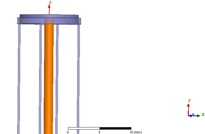
I've tried to simulate a structure in HFSS like a bit of coax, but with just 4 wires for the braid. 50 Ω wave ports were attached to each end, so both ends of this antenna/coax are terminated. This is 100 mm long, the inner conductor has a diameter of 1.5 mm and the outer conductors each have a diameter of 0.4 mm. The overall diameter is 10.4 mm, as the wires on the outside are offset 5 mm from the centre. I must admit, the wires are thinner than I was intending, but that was a result of playing with the diameters to get a decent screenshot which I posted previously. But that aside, that's was what simulated. Perhaps the high aspect ratio, with very thin but long wires is causing HFSS a problem.
This structure will obviously radiate, as it is like a bit of coax with very little braid, but according to my HFSS model, this has some bizarre characteristics, which clearly make no sense, but I'm not sure why the simulation is so far off the truth.
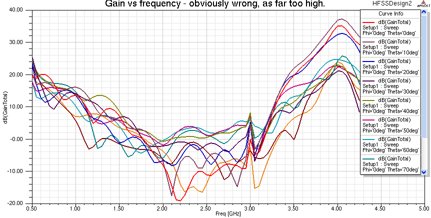
The frequency sweep was from 0.2 to 5.0 GHz, but for reasons I don't understand, when I plot the gain vs frequency, it starts at 500 MHz, not 200 MHz.
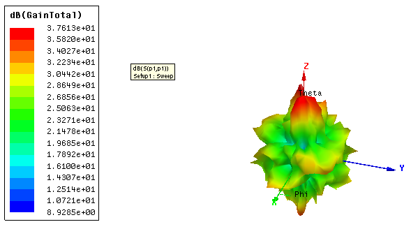
A plot of the radiation pattern at 4.05 GHz is shown. This is the frequency at which the gain is seen to be highest, and is around 37.6 dBi.
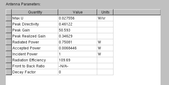
An inspection of the antenna parameters reveal this is very odd. As it has an efficiency of about 110 (or 11000 %), with a total radiated power 110 times the accepted power. The peak gain, of 50.593 is 17 dBi, but the gain shown on the graphs is well above 17 dBi, at around 37.6 dBi.
A plot of the S parameters look semi-believable:
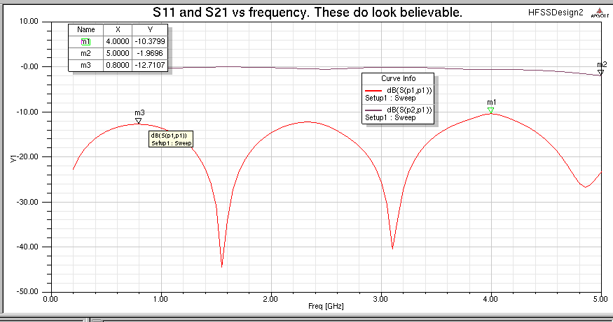
The S parameters would indicate that there is a periodic loss of power between the input port and output port (S21), and the changes are related to the S11. I was expecting.this to radiate most when λ/2 long, and at odd multiples of that, but it seems to radiate most at 800 MHz. Note how these S parameters are plotted from 200 MHz to 5 GHz, but the gain is only plotted above 500 MHz, despite I had selected all the frequencies when making the gain plot, and 200 MHz was one of those frequencies.
I'm wondering what went wrong. The solution frequency was set to 1.5 GHz, as that is the frequency at which the 100 mm long structure is λ/2 long, and where I might have expected it to radiate most. The S11 and S21 plots would tend to indicate this is not the case, and maximum radiation would occur at half this frequency, so when λ/4 long, but its anyone's guess how accurate the S parameter plots are, given some other results are clearly very wrong.
I've attached the .hfss file if anyone wants to look. But be aware, it took about 6 hours to simulate on two quad-core 3.16 GHz Xeons and used 18.5 GB of RAM.
Any thoughts what is wrong? I'm suspecting there might be an issue with the ports. I have used waveports inside the airbox, and have put a PEC cap on each. I'm not confident the ports are set properly.
These sort of things are what often worries me with computer simulations. It is sometimes possible to get an erroneous result and one will not know. In this case, the results are so odd that there is obviously a problem. But in other cases, results can look believable when they are junk.
There are a couple of things I have changed from the HFSS defaults.
Deborah
This structure will obviously radiate, as it is like a bit of coax with very little braid, but according to my HFSS model, this has some bizarre characteristics, which clearly make no sense, but I'm not sure why the simulation is so far off the truth.
The frequency sweep was from 0.2 to 5.0 GHz, but for reasons I don't understand, when I plot the gain vs frequency, it starts at 500 MHz, not 200 MHz.
A plot of the radiation pattern at 4.05 GHz is shown. This is the frequency at which the gain is seen to be highest, and is around 37.6 dBi.
An inspection of the antenna parameters reveal this is very odd. As it has an efficiency of about 110 (or 11000 %), with a total radiated power 110 times the accepted power. The peak gain, of 50.593 is 17 dBi, but the gain shown on the graphs is well above 17 dBi, at around 37.6 dBi.
A plot of the S parameters look semi-believable:
The S parameters would indicate that there is a periodic loss of power between the input port and output port (S21), and the changes are related to the S11. I was expecting.this to radiate most when λ/2 long, and at odd multiples of that, but it seems to radiate most at 800 MHz. Note how these S parameters are plotted from 200 MHz to 5 GHz, but the gain is only plotted above 500 MHz, despite I had selected all the frequencies when making the gain plot, and 200 MHz was one of those frequencies.
I'm wondering what went wrong. The solution frequency was set to 1.5 GHz, as that is the frequency at which the 100 mm long structure is λ/2 long, and where I might have expected it to radiate most. The S11 and S21 plots would tend to indicate this is not the case, and maximum radiation would occur at half this frequency, so when λ/4 long, but its anyone's guess how accurate the S parameter plots are, given some other results are clearly very wrong.
I've attached the .hfss file if anyone wants to look. But be aware, it took about 6 hours to simulate on two quad-core 3.16 GHz Xeons and used 18.5 GB of RAM.
Any thoughts what is wrong? I'm suspecting there might be an issue with the ports. I have used waveports inside the airbox, and have put a PEC cap on each. I'm not confident the ports are set properly.
These sort of things are what often worries me with computer simulations. It is sometimes possible to get an erroneous result and one will not know. In this case, the results are so odd that there is obviously a problem. But in other cases, results can look believable when they are junk.
There are a couple of things I have changed from the HFSS defaults.
- The length of a tetrahedral on the radiation boundary was set to 10 mm, so the radiation pattern is correctly calculated at the highest freuqency
- I wanted two consecutive converged adaptive passes. In fact, it converged with two passes, which is unusually few. But 3 passes are used.
Deborah
Attachments
Last edited: