Continue to Site

Welcome to EDAboard.com

Welcome to our site! EDAboard.com is an international Electronics Discussion Forum focused on EDA software, circuits, schematics, books, theory, papers, asic, pld, 8051, DSP, Network, RF, Analog Design, PCB, Service Manuals... and a whole lot more! To participate you need to register. Registration is free. Click here to register now.

What topology should I use?

Status
Not open for further replies.

L_jack_xing

Junior Member level 2
Joined
Nov 16, 2013
Messages
24
Helped
0
Reputation
0
Reaction score
0
Trophy points
1
Visit site
Activity points
186
I am designing a four output SMPS .Two output are isolated to primary and the others are not.The isolated outputs are 5V/50mA and 12V/500mA.The non-isolated ouputs are 3.3V/300mA and 15V/100mA.And What topology can give a best performance in this situation(except flyback)?Can you give me some advise? Thanks a lot.
 

The isolated outputs are 5V/50mA and 12V/500mA.

In this case it is reasonably efficient to drop the 12V to 5V using a linear regulating IC. Your power loss is 350 mW (7 x .05), which will not generate extreme heat.

To isolate the 12V, it can come from a transformer-based switching power supply.

Does a particular reason make you rule out a flyback? You probably know there are alternatives such as the forward, and the sepic, and the Cük types.
 

Does that 50mA load really need a LDO ?
I think the reason is that using a flyback in non-isolated situation is a little funny.LoL.
 

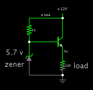
Of course a simpler method is to use this series regulator.
The power dissipation is low enough (350mW) that you can use a TO-92 transistor.

3530194700_1397583907.png


Here are questions to consider, as to the degree to which your supplies should interact.
* Do you intend to power a device which requires tight regulation?
* Will you apply sudden load changes on any of the supplies?

If the answer to either question is yes, then you may want to construct the supplies so that one does not derive from another.

- - - Updated - - -

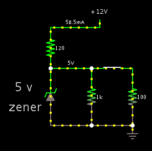
Come to think of it, is there any reason not to use a plain zener regulator?

7892457900_1397589088.png


With the switch closed, regulation is 5V. The safety resistor dissipates 410 mW.

With the switch open, it is 5.2 V. The zener endures 267 mW.
 

The circuit in the first picture I used once.But I used it in the IC‘s Vcc pin,I think,only with 5mA load.I will try if the project is
decided to do at last.Thanka a lot.:-D

The accurate demand of cross regulation I forget(two output 5%,the others 10%),I am very sorry. I think it is all right,as the load of each output is so low.But the real must be confirmed by practice.
 

For the non-isolated supplies, I guess you are aware of the basic smps converters.
Buck, boost, buck-boost.

It may be tricky to figure out where to connect a common ground for all your outputs, depending on what types of converters you use.

You might get more replies if you were to tell what kind of power source you have.
 

I am sorry.I was so busy that I had no time to follow the thread.I think the project has cancel and I have no chance to test it.
The detail :15V/100mA(regulation 10%,non-isolated) is used to supply IPM(intelligent power module).3.3V/300mA(regulation 5%,non-isolated) supply MCU.The other outputs are 12V/500mA(regulation 10%,isolated) and 5V/50mA (regulation 5%,isolated).I don't know what they use to.
I think a flyback is the best way to design this circuit.It is familiar to me.Haha.Thanks for help.
 

Status
Not open for further replies.

Similar threads

Part and Inventory Search

Welcome to EDABoard.com

Sponsor

Back
Top