Continue to Site

Welcome to EDAboard.com

Welcome to our site! EDAboard.com is an international Electronics Discussion Forum focused on EDA software, circuits, schematics, books, theory, papers, asic, pld, 8051, DSP, Network, RF, Analog Design, PCB, Service Manuals... and a whole lot more! To participate you need to register. Registration is free. Click here to register now.

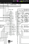
what is this terms stands for? : VL- VL+ etc..

Status
Not open for further replies.

motoshan

Junior Member level 2
Joined
Jan 1, 2014
Messages
22
Helped
0
Reputation
0
Reaction score
0
Trophy points
1
Visit site
Activity points
152
what are these terms stands for? : VL- VL+ etc..

What are these terms stands for?
VL+ VL-
VH+VH-

I found this labels when I opened my 8 year old home theatre. These are labelled near the transformer pcb.
Is this a high voltages to drive the power amp (STK 407) of the system.?
Can I convert this to a 12v with atleasr 3 Amps from these lines using any regulator?
Waiting for the advices.
 

Attachments

  • Screenshot_2014-09-13-20-12-16.png
    Screenshot_2014-09-13-20-12-16.png
    61.1 KB · Views: 561
Last edited:

I could not find a datasheet for an old Sanyo STK407 but people were talking about different sizes of it that had different output powers. Then it probably had different supply voltages. I do not know which one you have.
It probably uses a supply that is much more than 12V so the extra voltage times the 3A you want will create too much heat in the voltage regulator.
 
  • Like
Reactions: Eshal

    Eshal

    Points: 2
    Helpful Answer Positive Rating
thanks for the reply, So .. it is not ideal to use a 12v regulator right?
how can i test the voltage across these pins, Iam not an Electronic guru, or dont have too much experience with these stuffs. As you said STK407 070B is not available for me, What i had done was used a cheap 60W AMP tat is driven by 12V supply externally.This is only a temporary arrangement. But i need to make this as good as before since the STK is capable of delivering 100W RMS *2. So im planning to add a new STK or Power Amp to the Existing system.Kindly help me to test voltage across these pins.
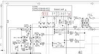
pls look at this image too
 

If the power amplifier is powered with +12V AND -12V then the total supply voltage is 24V. An amplifier is not perfect, it has losses so its maximum output is not 24V peak-to-peak, instead it is about 20V peak-to-peak.
20V peak-to-peak is 7.1V RMS which produces only 6.3W into an 8 ohms speaker or maybe 10W into a 4 ohms speaker.

100W into 8 ohms is a signal that is 28.3V RMS which is 80V peak-to-peak. Its amplifier would need a power supply that is about +44V AND -44V.

Your "60W" amp that is powered by 12V externally might be a car amplifier with 4 amplifiers inside (left front, right front, left rear and right rear) so each amplifier produces 15W "peak" into a 4 ohms speaker or about 9W "peak" into an 8 ohms speaker. 15W "peak" is 7.5W RMS and 9W "peak" is 4.5W RMS. Each of its amplifier has two amplifiers arranged in a bridge so that the 12V supply is effectively doubled to 24V. Peak power is fake power, RMS power is real true power.

Most power amplifiers DO NOT need a voltage regulator. STK amplifier modules were made by Sanyo but recently Panasonic took over Sanyo and the amplifier modules are not made anymore.
Notice on the schematic the power supply pins +VCC and -VCC are marked "!" which means DANGEROUS VOLTAGES. If you do not know how to measure the voltages in your amplifier with a multimeter then get an electronics geek to do it for you.
 
If the power amplifier is powered with +12V AND -12V then the total supply voltage is 24V. An amplifier is not perfect, it has losses so its maximum output is not 24V peak-to-peak, instead it is about 20V peak-to-peak.
20V peak-to-peak is 7.1V RMS which ....

Perfect.. thanks for the detailed information.
Definitely ill choose an assistance for my further steps.
 

Status
Not open for further replies.

Similar threads

Part and Inventory Search

Welcome to EDABoard.com

Sponsor

Back
Top